


We wers discussing the cooling system of the 3tonner's engine
Page 8
Page 9
Page 10
If you've noticed an error in this article please click here to report it so we can fix it.
in our last issue. We have a little more to say about it.
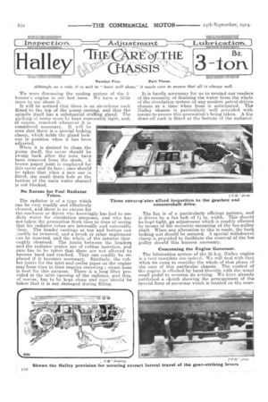
It will be noticed that there is an air-release coek fitted to the top of the pump casting, and that the spindle itself has a substantial stuffing gland. The packing ef hemp must 13.:f kept reasonably tight, and, of course, renewed whenever it in considered necessary. It will be seen that there is A, special locking clamp, which holds the gland locknut in position when it has been adjusted.
When it is desired to clean the pump itself, the cover should be swung back after the nuts have been removed from the studs. A brown paper joint is employed for this cover and its face ; care should be taken that when a new one is fitted, the small drain hole at the bottom of the main water channel is not blocked.
No Excuse for Foul Radiator Tubes.
The radiator is of a type which can be very readily and effectively cleaned, and there is no excuse for the mechanic or driver who knowingly has had to use dirty water for circulation purposes, and who has not taken the precaution from time to time of seeing that his radiator tubes are internally and externally 'lean. The header castings at. top and bottom can yew:lily be removed, and a brush or other implement can be inserted, and the whole of the interior thoroughly cleansed. The joints between the headers and the radiator centre are of rubber insertion, and care has to be taken that these are not allowed to become hard and cracked. They can readily be replaced if it becomes necessary. Similarly, the rubber joints for the inlet and outlet pipes on the engine may from time to time require renewing ; steam hose is best for this purpose. There is a long filter provided in the inlet opening of the radiator, and this, of Course, has to be kept clean and care should be taken that it is not damaged during filling.
It is hardly necessary for us to remind our readers of the necessity of draining the water from the whole of the circulation system of any modern petrol-dril.:•en chassis at a time when frost is anticipated. The Halley chassis is particularly well provided with means to ensure this precaution's being taken. A big draw-off cock is fitted at tho bottom of he radiator.
The fan is of a particularly efficient pattern, and is driven by a fan belt of 11 in. width. This should be kept tight, tn adjustment which is readily effected by means of the eccentric mounting of the fan-pulley shaft. When any alteration to this is made, the back locking nut should be secured. A special withdrawal clamp is provided to facilitate the removal of the fan pulley should this become necessary.
Concerning the Engine Governor.
The lubrication system of the 3'6 h.p. Halley engine is a very complete one indeed. We will deal with that when we conic to consider the whole of that phase of the care of this particular chassis. The control of the engine is effected by hand throttle with the usual small pedal to overrun its setting. We have already published a sketch showing the arrangement of the special form of governor which. is located on the near
side of the engine base. The governor itself is mounted on the main spindle, which drives the oil pump. The tension of the governor spring is adjusted by a special sleeve and locknut. There is a ball bearing providwl to take the thrust from this spring. Another adjustment for the governor is provided by means of an alteration to the length of the main pull-on lever near the throttle. Adjustment for the correct speed on the road is, of course, effected by means of alteration to the governor spring.
Clutch-gear Maintenance.
The clutch on the Halley is a straightforward job. Our last issue contained a. a reproduction of a crosssectional drawing through it. The main clutch spring, which is enclosed and central, is adjusted by means of a pair of locknuts, to which access is obtained through gaps in the central sleeve after the removal of the dirt cover, which is normally clamped in position. The nuts in question are provided with suitable tommy holes. As the leather lining to the cone wears down, the clutch, of course, enters the flywheel to a greater depth, and the adjustment as between clutch and pedal is modified. It therefore becomes necessary to make such alteration as will restore the pedal to its previous position relatively to the footboards. This may be effected by altering the screwed portion of the withdrawing gear, and subsequently relocking the nuts on it. The squared front end of the propeller shaft, where it engages with the extension of the clutch centre, may be readily lubricated through the same hole whilst the clutch is held out of engagement. Castor oil and grease mixed form a suitable lubricant at this point, it will be noted that no clutch stop is provided on this model. At the front end of the propeller shaft a special setscrew is provided to hold the squared joint in proper location.
The Halley Gearbox and Countershaft Drive.
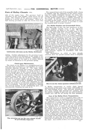
The first page of this, the last instalment of this article, includes several views of the capacious Halley gearbox, as fitted to this model. We may here warn users that there are certain holes in the gearbox flange which may, at first sight, appear to be minus their proper bolts or set screws. These, however, only exist on account of certain machining requirements, and there is no need to worry as to the replacement of something that may have dropped out. The whole box can be dropped very readily, as it is suspended at only three points, with the front end on a link. The gearbox itself is likely at any time to require very little in the way of adjustment. There is, however, the possibility, in connection with assembly or reassembly after stripping, of having to effect modifications ;As, loetween /fleshings of the various gears, in order that the change-speed lev-er shall correctly register in accordance with such engagements.
Our illustrations, to which we have already referred, show the special method which is adopted in Halley construction to enable slight lateral adjustments of the gears to be made with facility on the gear-striking levers. The pull-rods themselves have their forked ends screwed into position, and the effective lengths of such rods can, and should be, settled once and for all during the first assembly.
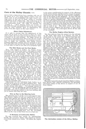
Care of the Halley Chain Transmission.
This chain-driven model is supplied either with or without chain cases, as required by each purchaser. We have embodied in the lubrication chart, which we published on page 43 of our last issue, concise directions as to the effective and regular lubrication of chains in either case. Above all, we would issue the reminder that, in order to get the best results from chain drive, it is necessary intelligently to use thelength adjustment which will be found on the radius rods, and when any such alteration is being made, the greatest care should be taken to insure that the adjustments on both sides are equal. In the course of Tong and varied experience, we have been astonished to find large numbers of instances in which practically no care has been taken to insure this balancing of adjustment as from one chain drive to the other. As a matter of fact, it is more usual than
not to find a chain-driven lorry running with one of its chains at a very much tighter tension than the other, and, in all probability, the. back wheels running more or less out of track, owing to unequal adjustment of the radius rods. One word more as to chains, and that we find well expressed by Halley's own instruction book. We make no apology for quoting it. "More driving chains are broken or damaged through unconsidered use of the foot brake than by their ordinary duty of transmitting the power from the engine to the road wheels."
About Chain Adjustment.
It is safe to assume that the adjustment of the chain will be more or less correct if, when the upper part is tight, the lower part can be moved about 11,-. in. vertically at its mid position. No chain should be used that is stretched more than 2 ins, for the length as found on this three-tonner. It is almost unnecessary to make the reminder that chains require detailed inspection whether they be encased or open. The split pins and special link bolts should be looked to from time to time to see that all is properly tight.
The Side Brake and the Foot Brake.
Now, with regard to brakes, the Halley design embodies very substantial types, with 'parts of ample area for heavy wear and tear, and good facilities for adjustment and replacement. The foot brake is mounted at the front of the gearbox, and is pedaloperated. To bring the pedal to the correct position, it is only necessary to lengthen or shorten the pullrod. There are springs below the shoes to stop chatter. To adjust for wear on the shoes, they can be brought closely together by the locked adjustment which will be found on top of the brake. There are two setscrews, which are provided in order to prevent the brakes' being pulled off too far. These, of course, must be located according to the best judgment of the driver or mechanic. The brakes on the hind wheels embody the pivoted loco-type shoes, which are fabric lined ; each is mounted on a hanger, which is kept up to its own position by powerful springs. The brake is by side lever, and is of the push-on type. This has been adopted, we learn, because in that way the off position is always in exactly the same place, and the driver's hand automatically finds it. The adjustment on the main pullrod is for assembly only. Adjustment for the individual back brakes is so obvious as to need no more than mention here. This is where modification to make up for wear and tear should always take place_ No attempt should be made to do this by altering the effective length of the pull-rods. It will be noticed that all the joints are provided with spring washers to prevent rattling, and yet to ensure that they are easy.
Give an Eye to the Steering Lock.
The steering gear is of the worm-and-segment type. The effective angles of lock are regulated by screws, which butt against the segment in the steering case. So far as the steering rods are concerned, the foreand-aft one is adjustable as to length at its rear end. Similarly, the offside end of the track rod is the one which is adjustable for width ; the other end is brazed. We again emphasize the importance of ensuring that these front wheels track correctly. The adjustment is a perfectly simple one, and if it be faultily reassembled, not only are unnecessary strains thrown on the whole of the steering gear, but the inevitable effect on the wear of the front tires is a bad one.
A Summary of Lubrication Duties.
We may conclude this article by summarizing, briefly, the necessary duties with regard to lubrication of the chassis as a whole. Of course the engine c12 is the prime consideration in respect of the efficiency of the whole chassis, and the need to ensure its proper lubrication has met with the most careful consideration at the hands of the designers. It rests with the user to see that these means are given every opportunity to operate satisfactorily. The circulation of the oil in the engine-case may be described as follows : the troughs below the big ends are first of all filled, and then oil overflows from them into the sump via a special filter, whence the eccentric twin-vane pump is able to suck it up. The shaft, which, as we have already stated, supports the governor, is that which drives the pump. It is skew-gear driven off the end of the camshaft.
The Halley Engine-oiling System.
• The first delivery from the pump is to the tell-tale on the dash, then down to a branch, one arm of which leads to the centre and forward bearings and the other to the back journal. The surplus goes via a feed pipe over the troughs. Instead of a cock to test the level in the crankcase, a plug is provided. The oil is distributed in the timing gearcase by tha skew-gear, which picks it up after it is delivered from the pump into a pocket, and is then distributed to the pocket over the front camshaft bearing, and thence to the front main bearing. The other camshaft bearings are oiled by splash into pockets inside the crank chamber. The whole system of lubrication is plainly shown in the diagram which we reproduce. One of the most important points which calls for regular lubrication is the clutch collar. A special lubricator is provided on the dashboard, and this has to be adjusted steadily to yield five drops a minute. Care should be taken that the union nuts on the flexible pipe which conveys this oil are kept tight, as they may have some tendency to work back, owing to the vibration set up from travelling over rough roads. An illustration on page 433 shows this method.
The gearbox should be filled to such an extent, that the level of the oil is within an inch below the shafts. There is an oil-retaining ring on the box with a fibre washer where the propeller-shaft drive enters the box. The lock-ring here must be kept tight. Our lubrication chart shows specially the methods which must be adopted to keep the chains properly lubricated, and, in particular, we recommend the boiling of the chains in hot tallow and graphite at intervals of not more than 5000 miles, after they have been properly cleansed from grit by soaking and brushing in a bath of paraffin.
The little instruction book issued by Halley's Industrial Motors, Ltd., usefully summarizes the principal lubrication duties of the driver in respect of one of these chassis.