


Patents Completed.
Page 20
If you've noticed an error in this article please click here to report it so we can fix it.
NON-SKID TIRE.— Kemp sh all.— No. 19,419, dated 28th August, 1907.—The tire (13) is provided with a series of circular stud-like projections (A), each being recessed at E. The studs are built well up on the tire and they merge into one another so as to present a flat tread surface.
SPEED INDICATORS.—Bailey.---No. 26,287, dated 28th November, 1907.—This invention relates to means for transmitting the motion of a road wheel to a speed indicator. Attached to the hub of the wheel is a flanged ring Of the inner periphery of which forms a track for rollers (d). The rollers (d) are carried by a leaf spring (r) secured to a bracket 0'1. The bracket (f) carries a short shaft (g) on which is mounted a. roller (h), bearing on the outer periphery of the ring (b). The spring (f) presses the rollers (//), and also the roller (h) against the ring (1). The motion of the roller (It) is transmitted to a speed indicator by means of a flexible shaft (i). A wire connection (j) is provided to prevent the device travelling round with the wheel.
TRANSMISSION SYSTEM.—Ward,-No. 21,439, dated 27th September, 1907.— This invention relates to a transmission system in which the engine drives a rotary pump; the latter, in turn, forces oil, or other fluid, to the rear axle for the purpose of transmitting motion. The rear axle (E) is hollow and divided longitudinally by a web (F) so as to form two conduits (G, G2), each provided with a port (H, H2), which open into separate annular chambers (1, P) within the casing attached to the hub of the wheel. Arranged within the casing are sun and planet wheels, the sun wheel (A) being rigid upon the stationary axle (E). The planet wheels (B, C, D) are mounted upon fixed pins carried by the two outer sides
of the casing. The casing consists of a central disc (j), with flat sides having circular recesses to receive the planet wheels (B, C. D), and also having feed ports (K) and exhaust ports (L). The casing (J) together with the wheel is rotated on the axle (E) by oil, which is forced by the pump iato one of the annular chambers, and thus into the feed ports (K). These feed ports open upon a number of exposed teeth on each of the wheels (13, C, D), the opposite sides of the wheels being open to the exhaust ports (I). The wheels are thus rotated, and travel with the casing round the centre wheel (A), the oil between the teeth being forced round to the exhaust ports (LI.
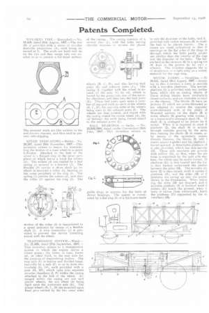
BALL BEARINGS. — Sachs. — No. 13,349/1908, dated (under Convention) 25th June, 1907.—This invention relates to guide rings or spacers for the balls of thrust bearings. The spacer is constituted by a flat ring (5) of a thickness made
to suit the diameter of the balls, and it provided with radial recesses (6) to enah the ball to be placed therein. The e cesses are made cylindrical so that tlopenings on the flat sides of the rings (5 through which the balls partly projec are smaller than the interior of the cage arid the diameter of the balls. The bal are held in the recesses (6) by a spring nil i8) kept in the groove by its own r siliency. The inventor suggests the ul of aluminium or a light alloy as a suitab material for the cage ring.
MOTOR LORRY.— Trouilliez.—Ni 19,025, dated 23rd August, 1907.—Accov ing to this invention a lorry is provide with a movable platform. The movab platform (2) is provided with two inclint faces, which rest on sliding blocks (8 These sliding blocks have similarly-ii clined surfaces, and are slideable in tree] on the chassis. The blocks (8) have pe jections (7) which are screw-threaded ar are adapted to receive the opposite: screw-threaded ends of the shafts R. Mounted midway on the shafts (3) a: worm wheels (61 gearing with worms ( on a transversely-arranged shaft (4). TI shaft (4) is arranged to he driven by ti motor, When it is required to raise ti platform (21, the shaft (4) is actuatt through suitable gearing by the mote thus causing the shafts (3) to rotate, ar by means of the oppositely screw( threads thereon, the blocks (8) will I drawn nearer together and the platform ( forced upward. A detachable platform (1 is also provided, which has side membe (13). These side members are provich with rollers (15), so that, when the pie form is supported by the said side met hers, the whole may be easily moved. TI platform (11) is first loaded and the lot is then hacked underneath the platfor between the sides (13). The movable plr form (2) is then raised, until it carries ti platform (11), and the sides (131 of platform are swung up into the positi< shown in the illustration. When unloa ing, the sides (13) are dropped, and ti movable platform (2) is lowered until ti rollers (15) touch the ground, when t: lorry is driven from underneath, leavii the platform (II) supported by the si members (13).