


Stabilizer for Tippers
Page 66
If you've noticed an error in this article please click here to report it so we can fix it.
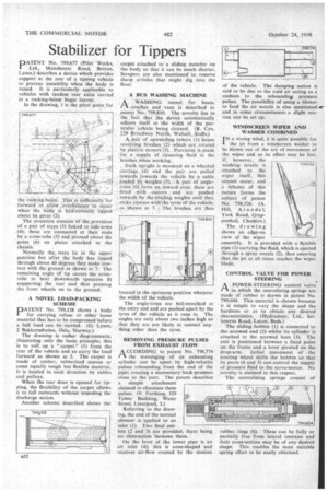
PATENT No. 799,677 (Pilot Works, Ltd., Manchester Road, Bolton, Lancs.) describes a device which provides support at the rear of a tipping vehicle to prevent instability when the body is raised. It is particularly applicable to vehicles with tandem rear axles carried
in a rocking-beam bogie layout. ' In the drawing, 1 is the pivot point for
the rocking-beim. ,This is itifficiently-far forward to ,allow Loverbalance to occur when the batty is hydraulically tipped about its pivot (2).
The invention consists of the provision of a pair of stays (3) linked to side-arms (4); these are connected at their ends . by a cross-tube (5) and pivoted about the point (6) on plates attached to the chassis.'
Normally the, stays lie in the upper position but after the body has tipped through about 40 degrees they make contact with the ground as shown at 7. The remaining angle of tip causes the crosstube to bear downwards (position 8) supporting the rear and thus pressing the front wheels on to the ground.
A NOVEL LOAD-PACKING SCHEME
PATENT No. 799,138 shows a body for carrying refuse or other loose material that has to be compressed before a full load can be carried. (G. Lyrics, 2 Bakkerudvcien, Oslo, Norway.)
The drawing is rather diagrammatic, illustrating only the basic principle; this is to roll up a "carpet" (I) from the rear of the vehicle and so carry the load forward as shown at 2. The carpet is made of rubber, rubberized canvas or some equally tough but flexible material. It is hauled in each direction by cables and pulleys.
When the rear door is opened for tipping, the flexibility of the carpet allows it to fall outwards without impeding the discharge action.
Another scheme described shows the carpet attached to a sliding member on the body so that it can be much shorter. Scrapers are also mentioned to remove sharp articles that might dig into the floor.
A BUS WASHING MACHINE
PAA WASHING tunnel for buses, coaches and vans is described in patent No. 799,810. The novelty lies in the fact that the device automatically adjusts itself to the width of the particular vehicle being cleaned. .(1k.. Cox. 229 Broadway North, Walsall,. Staffs.) A pan' of upstanding tors (1) house revOlving. brushes (2) which are rotated by electric motors:(3).. Provision is made for a supply of cleansing fluid to the brushes when working.
Each upright is mounted on a wheeled carriage (4) and the pair are pulled inwards towards the vehicle by a cable loaded b'Y weights (5). A pair of angle
irons .. irons (6) form an inward stop; these are fitted with -castors and are pushed inwards by the-loading weights until they make contact with the tyres Of the vehicle, as shown at 7. r The brushes are thus ocated in the optimum position whatever the width of the vehicle.
The angle-irons are bell-mouthed at the entry end and are pushed apart by the tyres of the vehicle as it runs in. The angles are only about two inches high so that they are not likely to contact anything other than the tyres.
REMOVING PRESSURE PULSES FROM EXHAUST FLOW
A CCORDING to patent No. 798,774 I-1 the scavenging of an exhausting cylinder can be upset by high-velocity pulses rebounding from the end of the pipe; creating a momentary back-pressure close to the port. The patent describes a simple attachment claimed to eliminate these pulses. (V. Farthing, 329 Tower Building, Water Street, Liverpool, 3.)
Referring to the drawing, the end of the normal silencer is applied to an inlet (1). Two final outlets (2 and 3) are provided there being no obstruction between them.
On the level of the lower, pipe is an air inlet (4); this is cone-shaped and receives air-flow created by the motion of the vehicle. The damping action is said to be due to the cold air acting as a cushion. to the rebounding pressure pulses. The possibility of using a blower to feed the air nozzle is also mentioned lir and in some circumstances a slight suction can be set up.
WINDSCREEN WIPER AND WASHER COMBINED
I N a strong wind, it is quite possible for the jet from a windscreen washer to be blown out of the arc of movement of the wiper and so its effect may be lost If, however, the washing nozzle is attached to the wiper itself, this cannot occur, and a cheme of this nature forms the subject 'of patent No. 798,526. (A. Hill, Arundel, York Road, Grappenhall, Cheshire.) The drawing shows an edge-on view of the wiper assembly. It is prov.ded with a flexible pipe (I) carrying the fluid, which is ejected through a spray nozzle (2), thus ensuring that the jet at all times reaches the wiper blade.
CONTROL VALVE FOR POWER STEERING
A POWER-STEERING control valve 1-1. in which the centralizing springs are made of rubber is shown in patent No. 799,604.. This material is chosen because it is simple to vary the shape and the hardness so as to obtain any desired characteristics. (Hydrosteer, Ltd., Sebourne Road, Luton, Beds.) The sliding bobbin (1) is connected to the screwed end (2) whilst its cylinder is attached to the screwed bore (3). The unit is positioned between a fixed point on the frame and a lever pivoted on the drop-arm. Initial movement of the steering wheel shifts the bobbin so that its ports (4 and 5) can control the supply of pressure fluid to the servo-motor. No novelty is claimed in this respect.
The centralizing springs consist of rubber rings (6). These can be fully or partially free from lateral restraint and their cross-section may be of any desired shape. This enables the most suitable spring effect to be easily obtained.