


A• Sliding Roof for Heavy Vehicles
Page 58
If you've noticed an error in this article please click here to report it so we can fix it.
OODS which have to be loaded on to a vehicle by a crane necessitate the provision of an open-top vehicle, and if weather protection be necessary, this has to be given by the rather cumbersome and slow method of covering by tarpaulins. Something better for the job is shown in patent No. 677,446, which comes from J. Roscoe and Associated Coachbuilders, Ltd., Southwick, Sunderland.
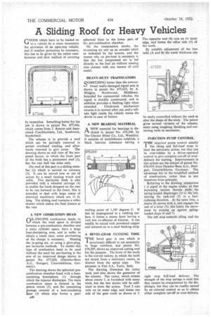
The scheme is to provide a roof which can be partially removed to permit overhead loading, and after wards returned to give cover. The drawing shows an end view of the proposed layout, in which the front part of the body has a permanent roof (1), but the rear half has sides only.
The roof of this part is a sliding member (2) which is carried on runways (3). It can be moved into or out of action by a small hauling winch and cable. This particular body is also provided with a wheeled carriage (4) to enable the loads dropped on the rear to be run forward to the front; this is intended to deal with large crates of electrical machinery which are 11 ft. long. The sliding roof contains a roller shutter which makes the final closure at the rear.
A NEW COMBUSTION HEAD OIL-ENGINE combustion heads, in which the total space is divided between a pre-combustion chamber and a main cylinder space, have a large heat-dissipating area, and in order to obtain a ready start, some pre-heating
of the charge is necessary. Heating the in-going air, or using a glow-plug, are favourite methods, To enable this type of combustion head to be used • without the need for pre-heating is the aim of an improved design shown in patent No. 677,020, (Daimler-Benz AG., Stuttgart, Unterttirkheim, Germany).
The drawing shows the spherical precombustion chamber lined with a heatinsulating hemisphere (1) through which the injector discharges. The main combustion space is formed in the piston crown (2), and the connecting passage consists of a heat-insulating liner (3) which also forms a part A40 spherical liner in the lower part, of th:. pre-combustion chamber.
On the compression stroke, the in-coming air sets up an annular whirl as indicated by the arrows, and the reason why no pre-heat is necessary is that the hot compressed air is led directly to the fuel jet without coming into contact with any masses of cold metaL HEAVY-DUTY TRAFFICATORS
QOMETHING better than the converts-) tional easily-damaged signal arm is shown in patent No. 677,623, by A. Midgley, Northwood, Middlesex. Intended for commercial vehicles, the signal is sturdily constructed, and in addition provides a flashing light when extended. Clockwork mechanism returns it to normal after use, and a telltale light inside the vehicle warns the driver in case of failure.
A NEW BEARING MATERIAL ANEW material for bearings is disclosed in patent No. 676,240, by The Glacier Metal Co., Ltd., Wembley. It consists of molybdenum sulphide, a black lustrous substance having a
melting point of 1,185 degrees C. If this be impregnated in a rubbing surface, it forms a smear layer having a very low co-efficient of friction. It can readily be mixed with powdered copper and sintered on to a steel backing strip.
A BEVEL-GEAR CUTIYING TOOL THE bevel gear is one which is notoriously difficult to cut accurately in large numbers, and patent No. 678,209, shows an improved cutting tool forthe purpose. The 'form of the tooth is the curved variety, in which the teeth are struck from a stationary centre, as
distinct from the spiral type. The patentee is Fiat S.A., Turin, Italy.
The drawing illustrates the cutter used, and also shows the geometry of the scheme. The cutter, which rotates about centre 1, is furnished with many tools, but the two shown will be sufficient to show the action. Tool 2 cuts only on its outer edge, and forms one side of the gear tooth as shown at 3. The opposite tool (4) cuts on its inner edge, and forms the other side (5) Of the tooth.
By suitable adjustment of •the two radii (A and B) the tooth thickness can be easily controlled without the need to alter the shape of the tools. The patent gives several variants of the scheme, some using roughing, finishing and correcting tools in succession.
• INJECTION PUMP CONTROL
MHE injection pump control usually
has idling and full-load stops to limit the automatic action, but they can be over-ridden by a driver-operated control to give complete cut-off or overdelivery for starting. Improvements in this system are the subject of patent No. 676,919, from Daimler-Benz A.G., Stuttgart, Untertfirkheim, Germany. The advantage lies in the simplified method of construction, rather than in any departure from principle.
Referring to the drawing, connection 1 is piped to the engine intake, sd that increasing suction therein pulls the spring-loaded diaphragm (2) to the left, moving the rack-rod (3) in a fuelreducing direction. At the same time, a sleeve (4) moves with it and engages the end of a lever (5); this limits the movement by coming up against springloaded stops (6 and 7).
The left stop 'controls idling, and the •
right stop full-load delivery. The strength of the stop springs is such that they cannot be overpowered by the diaphragm, but they can be readily moved by an external control so as to obtain either complete cut-off or over-delivery.