


SERVO CLUTCH OPERATION
Page 74
If you've noticed an error in this article please click here to report it so we can fix it.
PATENT No. 875,514 comes from Clayton Dewandre Co., Ltd., Titanic Works, Lincoln, and deals with the power operation of clutches. The aim of the design is to provide a very rapid release, but. to permit engagement at a controlled rate.
HYDRAULIC BRAKE FAILURE DATENT No. 877,401 deals with a safety device for use with hydraulic or air brakes. It consists of a unit that will isolate any line that loses its pressure. The patent comes from H. Stevenson, 45 Queen Street, Brisbane, Australia.
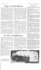
BRONZE BIG-ENDS
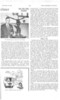
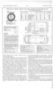
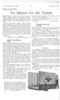
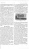
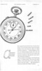
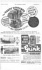
A BIG-END bearing made entirely of Z—V high-strength bronze forms the subject of patent No. 875,417. The aim is to provide a safety surface in case the softer lining should break down and to overcome production difficulties in Vee engine connecting rods. (Daimler-Benz A.G., Stuttgart-Untertiirkheim, Germany.)
As shown in the drawing, the steel connecting-rod (1) has bolted to it the halves of the bronze big-end. The mating faces are serrated (as shown at 2) and dowelled to ensure precise alignment in assembly. A lead or tin-based wearing surface is applied to the bore (3) and the running surface for an auxiliary connecting rod (4) by electro-deposition, the thickness of which is only a few thousandths of an inch.
Note the set-in of the bolts at the top; the reason for this is to reduce the overall width so that the rod can be taken out through the cylinder bore when dismantling.
SLOW-MOVING VEHICLE
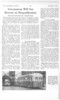
PATENT No. 869,470 comes from A Rover Co., Ltd., Meteor Works, Solihull, and shows a vehicle provided with an extra-low gear driven by an auxiliary engine. Its purpose is snow clearance, crop spraying, road sweeping and similar duties requiring only a crawling pace.
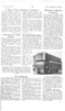
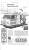
MOBILE PNEUMATIC POWER PLANT
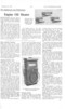
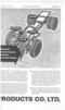
I-1 A VEHICLE designed expressly for
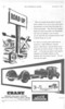
supplying compressed air to a working site is shown in patent No. 875,365. The novel feature is that the engine is designed to drive the compressor and the propulsion of the vehicle is only a secondary duty. (R. Clarke, 21 Raymond Road, London, S.W.19.) The drawing shows the general laycut. The engine (1) is of a type suitable for driving the compressor (2) through a dog clutch housed in the box (3).
At the other end of the engine is a conventional clutch and gearbox (4) for driving the vehicle via a propeller shaft (5). To limit the torque applied to the transmission, an intermediate gearbox (6) is used; this gives an overdrive effect. An accelerator pedal controls the engine when travelling, but when the compressor is driven a suitable governor takes c har ge. Interlocking devices are also described in the patent. LOW-FRICTION BALL JOINTS
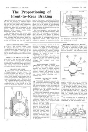
THE latest in ball-joint design is dis closed in patent No. 875,003 whid deals with joints having low-frictiol working surfaces. The scheme is parti
cularly suitable for use in suspensio systems. '(The Glacier Metal Co., Ltd 368 Ealing Road, Alperton, Middlesex
The drawing shows a typical joint i which a rod projects from both side. It comprises a steel ball (1) and a pal of part-spherical cups (2). These at held in assembly by a channel-scctio ring (3). Rubber rings (4) are unck compression and ensure a close sphericz fit.
The clamping ring is screwed on t outside and carries a ring-nut (5) f attachment to the surrounding part.