


Two Interesting Clutches
Page 56
If you've noticed an error in this article please click here to report it so we can fix it.
A Resume of Recently Published Patent Specifications; Copies of which, price Is., can be obtained from the
Patent Office
"Do ATENT No. 399,421 bears the well known name of Hardy Spicer and Co., Ltd., Birmingham, and refers to a new speed-responsive clutch. The object is to provide an automatic • mechanism which will eve a smooth take-up and be durable and economical • to manufacture. ,
In the diagram, which shows one form of construction, 11 is the flywheel, and 14 the driven shaft. The clutch ring (16) is gripped between two fabric rings in the usual manner, these being pressed together by a ring. The necessary pressure is supplied by centrifugal action by means of a weight (32), shown in black. This appears to be one of a number of weights disposed around the flywheel, and is shown at rest ; that is, in the free-clutch position.
When revolved at a certain speed, these weights tend to fly outwards, and the small stepped heel (33) is then tilted, thus applying pressure between the clutch plate and an abutment plate. Springs are provided on this abutment plate to ensure a gentle take-up. In addition, an alternative manual control by normal means is provided..
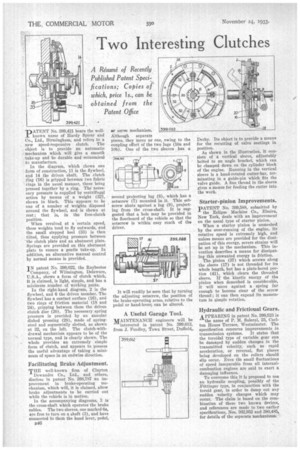
IN patent No. 399,022, the Raybestos Company, of Wilmington, Delaware, U.S.A., shows a form of clutch which, It is claimed, is light, simple, and has a minimum number of working parts.
In the right-hand diagram, 2 is the flywheel, and 6 the driven member. The flywheel has a contact surface (16), and two rings of friction material (18 and 24), gripping between them the driven clutch disc (20). The necessary spring pressure is provided by an annular dished pressing (28), made of springsteel and segmentally slotted, as shown at 32, on the left. The clutch-withdrawal mechanism appears to be of the normal type, and is clearly shown. The whole provides an extremely simple form of clutch, and appears to possess the useful advantage of taking IL minimum of space in an endwise direction.
Facilitating Brake Adjustment.
THE well-known firm of Clayton Dewandre Co., Ltd., and others, disclose in patent No. 398,787 an improvement in brake-operating mechanism, which will, it is claimed, allow brake adjustments to be carried out while the vehicle is in motion.
In the accompanying diagrams, 3 is the cross-shaft which operates the brake cables. The two sleeves, one marked 6a, are free to turn on a shaft (3), and have connected to them the hand lever, pedal, or servo mechanism. Although separate pieces, they move as one, owing to the coupling effect of the two lugs (10a and lob). One of the two sleeves has a
second projecting lug (8), which has a setscrew (7) mounted in it. This setscrew abets against a lug (9), projecting from the cross-shaft. It is suggested that a hole may be provided in the floorboard of the vehicle so that the setscrew is within easy reach of the driver.
It will readily be seen that by turning the adjusting setscrew, the position of the brake-operating arms, relative to the pedal or hand-lever; can be altered.
A Useful Garage Tool.
MAINTENANCE engineers will be interested in patent No. 399,612, from J. Fondley, Town Street, Duffield,. Derby. Its object is to provide a means for the recutting of valve Beatings in position. As shown in the illustration, it consists of a vertical sleeve, adjustably bolted to an tingle bracket, which can be clamped down on the cylinder block of the engine. Running in the vertical sleeve is a hand-rotated cutter-bar, terminating in a guide-pin which fits the valve guide. A fine thread in the sleeve gives a means for feeding the cutter into the work.
Starter-pinion Improvements.
PATENT No. 399,588, submitted by
PATENT
Eclipse Machine Co., Elmira, New York, deals with an improvement on the usual type of starter pinion. When a starter pinion is unmeshed by the over-running of the engine, its rotative speed is extremely high, and unless means are provided for the dissipation of this energy, severe strains will be set up in the mechanism. This invention describes a means for dissipating this unwanted energy in friction.
The pinion (37) which screws along the sleeve (17) is not threaded for its whole length, but has a plain-bored portion (41), which clears the threaded sleeve. If the kinetic energy of the pinion when demeshed is considerable, it will move against a spring far enough to become clear of the screw thread ; it can then expend its momentum in simple rotation.
Hydraulic and Frictional Gears.
APPEARING in patent No. 399,523 is the name of P. M. Salerni, 23, Carlton House Terrace, Westminster. The specification concerns improvements in transmission systems. It states that the toroidal type of variable gear can be damaged by sudden changes in the transmitted velocity, such as rapid acceleration, or reversal, fiat places being developed on the rollers should slip occur. Even tin small fluctuations of speed inseparable from all internalcombustion engines are said to exert a damaging influence.
To overcome this it is proposed to use an hydraulic coupling, possibly of the
• Fottinger type, in conjunction with the toroid gear, in order to damp out any sudden velocity changes which may occur. The claim is based on the combination of these two known devices, and references are made to two earlier specifications, Nos. 362,952 and 380,485, for details of the separate mechanisms.