


THORNYCROFT UNIVERSAL JOINT.
Page 36
If you've noticed an error in this article please click here to report it so we can fix it.
• A Résumé of
Recently Published Patent Specifications.
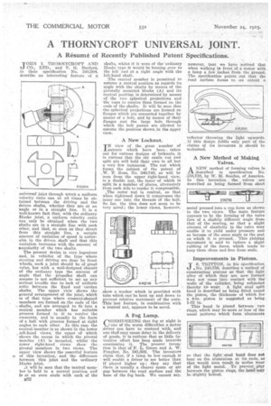
TOLIN I. THORNYCROFT AND CO., LTD., and V. G. Barford, in their specification No. '240,504, describe an interesting feature of a oniversal joint through which a uniform velocity ratio can at all times be ob-. Wiled between the driving and the driven shafts, whether they are at an angle or in a straight line. It is a well-known fact that, with the ordinary Hooke joint, a uniform velocity ratio can only be obtained when the two shafts are in a straight line with each other, and that, so soon as they divert from this straight line, a certain amount of variation of speed is noticeable in the driven shaft and that this variation increases with the amount of angularity of the two shafts.
The present device is very ingenious and,. in vehicles of the type where steering and driving are done by front wheels, such a joint should be of great value, but with a well-designed chassis of the ordinary type the amount of angle that the propeller shaft can assume is not sufficient to set up any Serious trouble due to lack of uniform ratio between the fixed and cardan shafts. The upper view shows the general arrangement of the joint, which is of that type where crescent-shaped members are formed on,the ends of the shafts,and are arranged to fit into a central member which has suitable grooves formed in it' to reeeive" the crescents, and is usually in the forn of a hall with grooves formed at right angles to each other. In this case the central member is as shown in the lower left-hand views, the upper of which shows the recess in which the pivotal member (A) is mounted, whilst the lower right-hand views show the pivotal members in two views. The upper view glows the essential feature so, of this invention, and the difference between this joint and the -ordinary Hooke joint.
;t will be seen that the central member is held in a central position and Is at an even angle with each of the B52 shafts, whilst if it were of the ordinary Hooke type it would be leaving over to the left and at a right angle with the left-hand shaft.
The central member is permitted to assume a central position as regards its angle with the shafts by means of the pivotally mounted blocks (A) and its central position is determined by means of the two spherical projections and the cups to receive them formed on the ends of the shafts. It will be seen that the spherical projections are formed on flanges which are connected together by means of a bolt, and by means of their flanges and the large hole through which the bolt passes are allowed to assume the position shown.in the upper view.
A New Locknut.
IN view of the great number of Patents which have been, taken out for various designs of Iocknuts, it is curious that the old castle nut and split pin still hold their own in all but a very few instances. The nut which forms the subject of the patent of W. T. Ross, No. 240,746, as will be seen from the upper right-hand view, is a double nut, the inner of which is split in a number of places, alternately from each side to render it compressible. „.The .outer nut is conical, so that when tightened dawn it compresses the , inner one into the threads of the bolt. So far, the idea does not seem to be very novel; the lower view, however, show a washer which is provided with tabs which can be bent up and down to prevent relative movement of the nuts. -trhis last feature, in combination with a conical nut, appears to be novel.
A Fog Lamp.
ONSIDERING that fog at night is `1..) one of the worst difficulties a motor .driver can have to contend with, and one that may cause delay in the delivery of goods, it is mil-ions that so little inventive effort has been made towards overceming it. The present invention is that of F. L. Green and A. W. rougher, No. 241,502. The inventors claim that, if a lamp be low enough it will enable a driver to see better than if placed higher up ; they say that there is usually a clearer space or air gap between the road surface and .the base of the fog bank. We cannot say, however, tnat we have noticed that when walking ih front of a motor with a lamp a few inches from the ground. The specification points out that the road surface forms to an extent a
reflector throwing the light upwards. If this design fulfils only part of the claims of its inventors it should be Welcomed.
A New Method of Making Valves.
A NEW method of forming valves is ..C1L described in specification No. 228,728, by W. NI. Searles, of America. In this invention the valves are described as being formed from sheet
metal pressed into, a cup form as shown in the two views. The main feature appears to be the forming of the valve face of a slightly different angle from that of the seating, so that a slight amount of elasticity in the valve may enable it to yield under pressure and so become of the same angle as the seat on which it is pressed. This yielding movement is said to induce a slight rubbing of the faces, which tends to keep them clean and free from scale.
Improvements in Pistons.
TS. TRITTON, in his specification .No. 240,756, describes a method of constructing pistons so that the light alloy of which they are now formed does not come into contact with the walls of the cylinder, being subjected thereby towear. A light steel split band is described as being fitted round the piston, the thickness of which for a 4-in, piston is suggested as being 1-32 in.
This hand is placed between two rings, which may be more or less of the usual pattern-, which form abutMents
so that the light 'steel band does not bear on the aluminium at its ends, as that would. soon result in undue wear of the light metal. To prevent play between the piston rings, the band may be slightly helical.