


A Résumé of Recently. Published Patent Specifications
Page 54
If you've noticed an error in this article please click here to report it so we can fix it.
Petrol Injection as an Anti detonant
PATENT No. 596,846 gives some interesting observations on the causes of knocking, and suggests a means by which it can be abolished. The patentee is the Texaco Development Corporation,
Wilmington, Delaware, U.S.A.
The chief cause of detonation is the autoignition of the " end-gas " by the pressure rise caused by the burning of the first part of the charge. Dopes, such as lead compounds, and local cooling devices —the Ricardo head, for example—mitigate the evil to some extent, but do not abolish it, and even with these aids it is said to be impracticable to exceed a ratio of 7i to I.
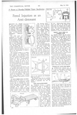
The proposed remedy is to employ petrol injection in conjunction with spark ignition. The drawing outlines the scheme, which .incorporates a fuel tank (1), pressure pump (2), storage chamber (3) and a variable-delivery injector (4). The fuel. can be preheated, if desired, by means of an electrically warmed coil (5). In operation, the shrouded inlet valve (6) admits air and sets up a swirl which persists throughout compression.
The injector sprays downstream and the sparking plug ignites the mixture immediately after the fuel issues from the nozzle. By this means, any "endgas" can consist only of air plus traces of exhaust gas, neither of which can be ignited by compression. The patent gives several pages of data resulting from the fitting of the system to various engines.
AN OIL-LUBRICATED CLUTCH
On., between the plates of a clutch will give an exceptionally smooth take-up, but to transmit the usual torque will require an engaging force of up to 10 times the normal. A clutch employing• oiled plates, with a hydraulic unitto supply the force, forms the subject of patent No. 596,908, which comes from H. Hobbs, 28, Woodcote Road, Leamington Spa.
The drawing shows a section of the proposed clutch, which is, in its essentials, of conventional form. But instead of having engaging springs, it has a number of light springs which tend to separate the plates. To press the plates together, a rubber-like bag (1) is used; this can be inflated by oil supplied by a pump (2). The oil, is fed to the bag at an outer point (3) where the pedal-operated control valve is situated.
The oil pump also provides a flow for lubricating the clutch plates; this escapes from passage 4 and reaches the plates by centrifugal action. The control valve is so arranged that when the engaging force is applied, the oil supply to the plates is cut off, and vice versa. This ensures that the oil squeezed from between the plates is not replaced until disengagement next occurs.
The inventor states that by carefully adjusting the oil flow at low engine speeds, a controlled slip can be obtained, NEW CONTAINER BODY
AVEHICLE having a quickly detachable body is described in patent No. 596,285 by A. Prentice, Westerdale, Centenary Avenue, Airdrie, Lanarkshire. The aim is to load and unload without the necessity of detaining the vehicle, which could be working with another body.
The drawing illustrates the essentials of the scheme, and shows the body in the process of detachment. It is adapted to receive a pair of jacks (1) at the front and a single twinwheeled jack (2) at the rear. Quick-acting hook clamps secure the body to the chassis, and when these are released, and the body raised clear, the vehicle can be driven away. For speed in detachment, the securing clamps can be locked or released by a lever in the driver's cab.
FRONT AXLE USED AS TORSION BAR
ANOVEL scheme for the lateral
• stabilization of a vehicle is shown in Intent No. 596,899 by the Ford Motor Co., Ltd., 88, Regent Street, London, W.1. Aimed principally at preventing body roll, the scheme utilizes the front axle as a torsion bar.
The well-known Ford transverse springing is used, but the radius rods (1) are formed into jaws at point 2, where they meet the front axle, which is clamped firmly between them. The radius rods project forward of this point to carry the spring ends. The radius rods, at their rear ends, are splined and clamped to a short torsion bar (3) located on the chassis.
As the axle, the radius rods and the torsion bar form a closed and locked figure, it will be appreciated that if one corner be lifted, deflection must occur. The radius rods are the strongest members, so that the deflection is shared between the torsion bar and the front axle. This means -that a much lighter construction can be employed.
HYDRAULIC JACK FOR SHOPS
AHYDRAULIC wheeled jack, as used in repair shops, is described in patent No. 595,522 by H. Page, Alhambra, California, U.S.A. A
novelty of the design is the provisio, of two lifting ratios, a fast one for positioning and a slow, powerful one for the actual lift.
In the drawing, the lifting arm (1) can be raised about a pivot (2) to the fulllift position shown in broken lines. The motive power is a hydraulic piston (3) which is worked by a multi-stroke hand pump shown generally at 4. The piston and its cylinder are slightly stepped at the point 5, so that a narrow annular space is created when the piston moves.
Initially, the working fluid is fed to this space by a port (6), thus giving a rapid lift. When resistance is encountered,a spring-loaded ball valve is forced open, an action which diverts the fluid to the main piston.