


A Hydraulic Tailboard
Page 60
If you've noticed an error in this article please click here to report it so we can fix it.
THE use of the tailboard of a lorry as a lift for the load is the subjecr of patent No. 633.588. -The patentee is
D. Layton, Tudor House, Polar Avenue, Eaton, Norwich. and his scheme is intended to facilitate the attachment of the unit to_an existing vehicle.
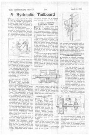
A pair of box-section girders is attached by sturdy -brackets (I) to the chassis, being extended both upwards and downwards. Sliding on the girder is a channel-sec-ton member (2) having inturned edges to embrace the girder,
A hydraulic rani is loeated inside eac s box girder, and its lift is transmitted by a wire cable (3). This cable is attached to the piston. and runs pp the inside and' over a pulley at the top, to descend on the outside to carry the tailboard.
The hydraulic pipe connections
also emerge from the lop of the6 box girder, -whence they lead to the control valve and the pump.. The 'tailboard itself is suitably strengthened to withstand its additional duties.
ANEW ROTARY ENGINE.
Tdevelopment of the gas
-turbine has ' encouraged inventors to explore the possibilities of other forms of rotary
engine, and a new example is shown in patent No. 633,596 by 'Cornpagnie NOrmande d'Etudes .Pour l'Application de Procedes Mecaniques, • Iloorth, France. Theengine shOwn works Onthe y.---11-known 'principle of • using rotors having sliding vanes which sweep an eccentric space inside the, casing.
rile drawing shows a practical layout in which a pair of rotors is used, one being the power unit and the other a charging pump. The chief features are the main central shaft, the compressor rotor (1) and. the, power rotor (2), each fitted with a pair of diametrically opposed vanes which sWeep. the crescent-shaped-combustion space., To understand the working cycle requires eight drawings illustrating various points in the cycle; these are given in the specification.
The engine is said to be cheap to make and, owing to the high ratio of expansion possible, efficient in use. The expanslion also eliminates cooling problems, as the temperature of the exliaust is very low. A test engine hasbeen run Over a speed range of 4003.500 r.p.m. and has given promising results. Spark ignition can be used, or s higher compression and the compres a34 sion-ignition principle can be adopted whilst retaining the same basic design.
A " CONSTANT-HEIGHT SUSPENSION SYSTEM
D A TENT No. 613,384, comes from the B. F. Goodrich Co., New Yorke U.S.A., and discloses a new design for a suspension system. Rubber is used for the resilent member and means are incorporated to maintain the body at a constant height irrespective of the . load.
The drawing shows sufficient of the system tci illustrate its action. The resilient member. (1) is tubular and is filled with -rubber, centred upon a pair of stub shafts,,one of which is attached to the axle-casing at 2 and the other rotatable to the frame at 3. The outer "end 'of the axle is attached to the outer sleeve via an arm (4) so that rise and fall -of the axle puts the rubber 'in torsion.
The constant-height device consists of a hydraulic cylinder (5) the piston in , which makescontact with an arm (6) fixed to the central spindle of the spring unit:When the outer sleeve is forcibly rotated by a. change in load, a projecting arm (7-) operates a control valve onthe cylinder in a directban such -that it tends to restore the original position of the spring.
The hydraulic power is derived froin an engine-driven pump with the addition of a small accumulator. A dashpot is included in the con-trot-valve system so that it does. notecome into . action for small roadinequalities.
-TORQUE-CONVERTER . VANES
R . P. Salami, R . P. Salami, Lillibrooke Manor; Cox Green, Betts,' comes patent " No. 633, 595, which deals with improvements in the design of torque-converters. In the 'standard form of this unit there are three .elements, the primary impeller, an intermediate reaction member restrained to one-way rotation, and the output turbine. The present scheme refers to a modified form of the reaction member.
The vanes of a reaction member should .be kept as short axially as possible, and few in number, and it is the, 'aim of the inventor to achieve optimum values in this respect.
He achieves his end by using aspecial form of vane having a bulbous outline
and arranged to give an outlet angle to the fluid of about 70 degrees with the main axis. The vanes are placed close enough to prevent jiquid passing through without being deflected. The patent shows developments of the form of the blade at various diameters.
HYDRAULIC TRANSMISSION HAS VARIABLE-PITCH VANES
NOVELTV in hydraulic transmission is shown in patent No. 633,475, which comes from H. Bellamy. Row House. Wereham, King's Lynn. Th's inventor employs a vaned transmitter in which the dr'veti set has a variable pitch.
In the drawing. 1 is the engine-driven set, which has fixed vanes, and 2 Elia output member having variable-pitch vanes. The latter are mounted upon a 'series of rocking spindlei (3) centred in. bearings (4) on a rotating plate. To vary the effective angles, the spindles can be rocked by sliding a set of push'-rods (5). This can be
done by a hand control, or
entirely automatically by means of the apparatus shown in the rest a
the drawing , A screwed adjUsting sleeve (6) can be turned one way Or the other by one of a pair of oil motors (7). These are powered by a constantly running pump (8) and controlled by a master valve (9) which is, itself, controlled by a spring-loaded piston subject to thc oil pressure.
The inventor proposes to employ a gearbox which, ,it is suggested, should embody one forward speed of 1-to-1 ratio, a neutral position, and a reverse gear.