


• An Albion Overspeed Gear
Page 56
If you've noticed an error in this article please click here to report it so we can fix it.
A Resume of Patent Specifications that Have Recently Been Published PNo. 500,605 deals with an overspeed gear of. the type in which a slight speed increase rA ri be effected between the engine and the normal gearbox. The patentees are Albion Motors Ltd.. and J. Kemp, both of Scotstoun, Glasgow. The drawing shows a half-section on the axis of the primary shaft of the gearbox. The shaft (8) from the clutch carries a spider (5) fitted with 'planet pinions (3). The pinions mesh, on the outside, with an internal gear (2) fixed to the input shaft (4) of the normal gearbox. The planets mesh, also, with a free sun wheel (7), which carries a brake drum (1). A free wheel (6) prevents overrunning of the sun wheel, so that, if no constraint be applied, the whole mechanism revolves as a unit; if the drum (1) be braked, however, the epicyclic gear comes into action and effects a speed increase.
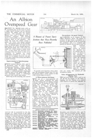
Improvements in Injection-pump Control.
FROM Leyland Motors, Ltd., and S. IVIarkland, both of Ham Works, Kingston-on-Thames, comes patent No. 500,365, describing improvements in injection-pump control. In this scheme, a suction-operated diaphragm controls most of the speed range, but, near maximum speed, a centrifugal governor also comes into action.
Referring to the drawing, the control
rack-rod (8) is connected to the diaphragm (1), which moves to the right under intake suction and is returned by a spring, a screwed stop (2) being used to adjust the slow-running position. The centrifugal governor moves a bellcrank (4), the motion of which is damped by an oil dash-pot (5). The bell-crank carries a tail (6) which, over most of the speed range, is away from arm 3, but, at high speeds, the tail abuts on an adjustable screw aid takes command of the rack-rod.
u30 To permit over-injection when starting, the maximum-output stop (7) can be 'moved until a notch comes in line with a screw-stop on arm S.
A Water-jacketed Oil Sump.
THE use of a water-jacketed oil sump, which performs the dual duty of cooling the oil during normal. working, and of heating it when cold, forms the subject of patent No. 499,884, by F. Tippen, 3, Eastleigh Avenue, Earlsdon, Coventry. With this arrangement, during normal running the water flows from the engine jacket to the radiator, and thence, at a lower temperature, through the sump jacket, whence it returns to the engine jacket.
When starting from cold, however, a thermostatic valve closes off the radiator, so that the circuit is confined to the engine, jacket and the oil
sump. This results in a quick and uniform warming-up of the whole engine, after which the normal flow is automatically re-established. Gas-producer Air-speed Control.
ACCORDING to H. Dupuy, 27 Rue du Banquier, Paris, the degree of richness of gas from a producer is a function of the speed of the air entering the producer, and, if a constant gas quality he desired the air speed must be
kept constant.
This inventor
shows, in patent No. 499,913, how he attains this object. As shown in the drawing, a semi-circular slidevalve (2) controls the area of the producer intake, whilst a similar valve (3) governs the air supply to the -engine intake pipe (1). The two valves are coupled, and are under the control of the accelerator pedal.
Valve Arrangements for Hydraulic Tipping Gear.
TO act as a safety valve, and to cut off the oil supply at the limit of tipping, are the objects of a control valve shown in patent No. 500,232, by Brornilow and Edwards, Ltd., and H. Swift, both of Foundry Street, Bolton. Union 3 receives oil from the pump, whilst union 2 is the return connection, and a third union, 5, leads to the ram cylinder. During lifting, fluid flows directly from the supply union (3) to the ram connection (5); should an overload occur the ball (4) is lifted from its seat and by-passes the oil. To limit the tipping angle, a sliding rod (1) is linked to the body so that, at the maximum angle, valve 6 is opened.