


A Pedestrian-Controlled Tilling Machine
Page 28
If you've noticed an error in this article please click here to report it so we can fix it.
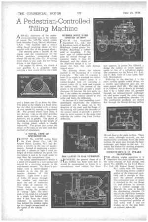
ASM ALL cultivator of the pedestrian-controlled type, is the subject of patent No. 617,726, which comes from M ulsifier Corp., Detroit, Michigan, U.S.A. The machine uses a rotary tilling barrel revolving about an axis parallel with that of the ground wheel'.
The drawing gives a section of the engine and the transmission to the driven members, comprising front , wheels (1) and the tiller (2). A trailing third wheel, is also used, but not being driven, is not illustrsted.
The engine (3) drives, via clutch 4 and gearbox 5, a propeller shaft carrying a slow worm (6) for the wheel
and a faster one (7) to drive the tiller. The drive to the wheels is a fixed ratio, but the tiller is provided with a choice of, two speeds -by moving a dog-clutch 1„8). The ground wheels have little, if any driving a do, as the tiller provides much more tractive effort; they can, • .however, act as guides. -The depth of working is controlled by the height of the trailing wheel; which is readily adjustable. The patent also covers the shape of the tines on the tiller and their method of attachment.
A NOVEL TYPE OF • • SPEEDOMETER
PATENT No. 619,789 comes from the Ford Motor Co.; • Ltd., 88, Regent. Street, London, W.1, and discloses a novelty in the way of speedometers. Instead of employing a pointer and dial. a column of light is used, the length of which indicates the speed. The instrument is said to be much easier to read than the conventional type.
,The actual speed-responsive device is a drum (1) coupled to a hair-spring and moved by a revolving magnet, in the well-known mariner. The drum is provided with a sector-shaped window in its rim, for an angular distance of 104 degrees. Light from a pair of bulbs (2) passes through . the window and impinges upon the end of numerous thin strips of material (3). These strips are made of plastic having the property of 'piping" light. The other ends of the strips are arranged in a single line behind window 4 and form the visual indicator. In operation, the line behind the window lights up to a length proportional to the speed of the vehicle.
A34 RUBBER JOINT WITH LIMITED ACTION
R 0 M the Associated 1 Equipment Co., Ltd., and G. Rackham, both of Southall, Middlesex, comes patent No. 619,618, describing a rubber joint or mounting. If the usual type of rubber-bushed joint be moved through an excessive angle, it may be damaged, and the object of the improved design is so to
mount the bush that such damage cannot occur
The drawing shows the scheme applied to the mounting of a rocking cross-tube. The tube (1) contains a bush (2) to which is attached the rubber sleeve (3). The central piece is a conical-headed bolt (4) carrying a 'conical collar (5) to hold and expand the rubber bush. The essence of the patent is the provision of only a small clearance (6) between the two parts. so that if the rubber be excessively loaded, a metal-to-metal contact occurs at this Point and limits the deflection.
In the case of a load exceeding a predetermined magnitude,the clearance mentioned will he taken up in the direction of the load, and the flange of the housing will contact the shoulder of the conical sleeve to provride a positive stop by metal contact, at the same time relieving the rubber ring from further deflection.
THE LATEST IN GAS TURBINES
HITHERTO, the general shape of a gas turbine has been such that it would be inconvenient to house in a conventional road vehicle, but there
now appears, in patent No. 620,461, Et design the outline of which approximates to that of a eylindered „engine. The patentees are the Rover Co., Ltd., and F. Bell, both of Lode Lane, Solihull, Birmingham.
Referring to the drawing, 1 is the main turbine spindle which drives, via a double spur-reduction gear (2), the main output shaft (3). The heat cycle is as follows: Air is drawn in through duct 4 by a laded rotor (5), pumped through an exhaust-heated exchanger (6), and passes round the outer casing to reach the •combustion chamber (7). The combustion products are ducted first through the blower-driving turbine (8) and then to the main turbine. These two units, although co-axial, are not mechanically connected. From the main turbine, the gases pass through the heatexchanger and thence to the exit. To rotate the blower for starting purposes. an electric motor (9) is provided.
IMPROVEMENTS IN INTAKE MANIFOLDS
FDR efficient engine operation it is important that each cylinder receives the same amount of fuel charge, and patent No. 620,251, by the Ford Motor Co., Ltd., 88, Regent Street, London,
W.1, treats with this feature.
The drawing shows a central section of the improved manifold, and is enough to illustrate the general principle. The carburetter (one or more) is attached to the top flange (I) and delivers its mixture into a Conical passage (2). Beneath the cone is located the diStributing chamber (3) and all the individual conduits (4) are led off from round the volumetric centre of the cone. Any unvaporized particles of fuel strike wall 5 and are broken up by the heat from an exhaust jacket (6).