


LONDON'S LEAD IN BUS DESIGN.
Page 15

Page 16
If you've noticed an error in this article please click here to report it so we can fix it.
In this Article we Deal with the Tilling-Stevens T.S.7 Chassis and the London-t)pe Body Built by Thomas Tilling, Ltd.
JN the first article of this series, which we included in our last week'S issue, we gave as part of the introdues tion a resume' of the main requirements of the London bus, as specified by Scot. land Yard, and we pointed out how modern design has approached so closely to the police limitations imposed that it has been a comparatively simple matter for some half-dorzen makers otf chassis to modify them slightly in order to pass Scotland Yard, and this without in any way making them unsuitable for work in the provinces or overseas. We followed this by dealing with two makes, and this week we deal with the petrol-electric chassis built by Tilling. Stevens Motors, Ltd., of Maidstone, and the body fitted to it, which is constructed by Thomas Tilling, Ltd.
The chassis is of particular interest, not only in view of the great progress which has been made, but also because of its remarkable system of power transmission from the engine to the rear wheels. In brief, the engine is coupled through a laminated steel spring to ail electric dynamo, the current from which is conveyed to a motor coupled to the front end of the propeller shaft of the overhead worm-driven rear axle. This gives a drive which has many distinctive features, and makes the chassis particularly suitable for passenger work., One of the main points is that the road speed is not governed by engine speed, for on a smooth, level surface the engine and dynamo may be running at quite a low speed; but developing sufficient current to turn the motor at a much higher number of r.p.m. so that the engine never has to be raced to give high road speed under these conditions. It is for this reason that the final-drive gear ratio is so low as 10-k to 1, which has the effect of reducing the stresses on the propeller shaft.
It must also be pointed out that by putting the motor into reverse the
vehicle cannot possibly run forward, except at a snail's pace, and, similarly, when ascending a hill the vehicle cannot run backwards at a dangerous speed, for on a gradient of 1 in 4 with full load the maximum possible uncontrolled backward speed has been proved to be 3 m.p.h. to,4 m.p.h. without employing brakes, thus 3hosving -the powerful automatic spragging effect. That this system is appreciated is shown by an order for 30 buses which has recently been completed for the Chinese General Omnibus Co., Ltd., whilst other Tilling. Stevens chassis of the forward-steering type are being put into service in Melbourne.
For London work the leading dimensions are :—Chassis; Wheelbase, 14 ft. 9 ins.; overall length, 20 ft. 2i ins.; ground to top of frame, 2 ft. 8 ins. (with loaded body). The placing of the driver beside the engine and the forward steering gear provide a free length of 14 ft. 01 in. from the back of the driver's seat to the end of the chassis frame. Here we must point out the difference between this chassis and that designed for provincial work, which can be built, with a wheelbase up to, and if specially required even greater than, 16 it. 6 ins.
The chassis weights are :—Front axle„ 1 ton 12 cwt.; back axle, 2 tons; total, 3 tons 12 cwt.; whilst the weights of the complete bus are:— Unladen weight, 5 tons; • weight loaded, front axle, 3 tons 7 cwt. 2 qrs.; back axle, tons 19 cwt.; total, 8 tons 6 cwt. 2 qrs. The seating capacity is 26 outside and 22 in, giving a total of 48. The provincial chassis is, as a rule, slightly hevier than that used for London, th0 saving in weight lathe latter
being effected by reducing the length of the main frame and in dispensing with what might be termed superfluous details, such as the lighting set, for, in the London bus, lighting current is provided from the main dynamo through thi3 medium of an Edison battery. There are two charging rates, for winter and summer respectively, these being under the control of the. driver. In some of the provincial buses a separate lighting
dynamo is driven by a link belt franya pulley fitted to the tail end of the armature shaft of the main dynamo. •
.Few. modifications were required to meet the London regulations. The standard silencer arrangements are entplayed, and all foz•k connections are nipped up to a _ working fit, whilst steady brackets are fitted to the brake rods and the controller connections.
Quick adjusters of o thei, hand-screW type are also fitted to both brakes, the
standard arrangement of the last-named being by expanding shoes operating in concentric drums, and, therefore, no alteration was required. Another point on the Landon vehicle is the fitting of a trough in the centre of the bonnet to lead water away from the magneto, etc., whilst a ball-bearing throttle spindle provides accurate adjustment without leakage. A new feature on all models is thecombined oil filler and level cock. Hardened-steel shims are provided tor valve tappet adiustment.
The body employed on the London buses run by Thomas Tilling, Ltd., is
built on most scientific lines. Every _effort has been made to eliminate all heavy ironwork, and to build the body in such a manner that the strength is maintained. This is effected by the use of concealed steel flitch plates, which are overlapped and jointed in su,c4 a nianner as to form a continuous band
• round the body, at the same time avoiding sharp angles at the corners. • The front of the body is constructed on the trussed-girder principle, There are six crossed trusses in all at the back of two 22 S.W.G. sheet-steet plates, which occupy the whole front of the. body under the windows, and are turned round the side pillars so that the screws are not placed in shear. Each truss cross-rod fits into a corner plate, which Li tagged right into the wood, thus pre• venting pressure of the truss member from forcing apart the joints. In addi
lion to thiS., there is a small truss-rod at each top back corner of the body. This prevents any lateral movement, does away with the need for plating and is much stronger.
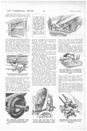
The arrangement of the platform brackets can hest he understood by referring to our sketch. Each bracket consists of a steel flitch, about 2i. ins, deep and & in. thick, which is curved up aleng the side of the chassis runner,
turned over the top of this and bolted right through to the chassis frame. Much saving of weight has been effected by the use of Bowden cushions, which are now standiirdized by the com pany. _ The ventilation is somewhat novel. At each side there are three ventilators which open in a forward direction and one at the rear which opens backwards, This last window is claimed to give a suction effect, which sets up eddies and draws the air through the ventilatois which face forwards.