


GIVING ACCESS TO THE CAB-ENCLOSED ENGINE.
Page 10
Page 11
If you've noticed an error in this article please click here to report it so we can fix it.
An Invention which Assists Materially in the Solution of a Problem which is Created by Placing the Seats for Drivers and Mates Beside the Engine.
THE DEVELOPMENT of the type of chassis which places the driver's position as far forward as possible beside the engine' therefore enclosing the engine either partially or wholly within the cab, has, of course, been necessitated by the desire to make the utmost use of the space behind the engine for loading purposes and without occupying more room than is necessary for the accommoda tion of the driver and the mate.
With the steering placed right forward and the engine enclosed as we have mentioned, the space on each side of the engine is used to the best advantage, and there is no.need then, for the purpose of control and operation, to encroach on what could be the full loading space of the vehicle. At the same time, the proportion of load borne by the front axle must be kept within reason, the price that has to be paid for these advantages being inaccessibility, to a greater or lesser extent, of the engine. If only a driver has to be accommodated, and not a mate, it is possible to erect a half cab on the off side of the engine and to locate every detail of the power plant that may require adjustment and attention on the near side, but when a complete cab is placed over the engine it almost certainly happens that consider able interference occurs. .
We have referred to this matter on previous occasions, and have urged the need to keep the load within the wheelbase, which means to say that the power plant may not be taken forward of the front axle—a method which might, at first sight, seem a possible solution of the problem.
Without having yet had time to gain substantial experience of the method covered by a patent speci
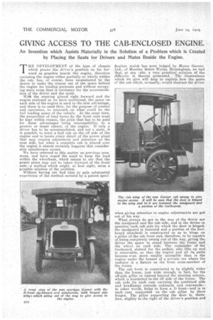
fication waich has been lodged by Henry Garner. Ltd., of Moseley Motor Works, Birmingham, we feel that, at any cate, a very practical solution Of the difficulty is therein presented. The illustrations which we give will help to explain how the parts o! the cab which, normally, would obstruct the driver when giving attention to engine adjustments are gob out of his way.
What always do get in the way of the driver are the mudguard and the cab side, and in the device in question each cab side (to which the door is hinged, the mudguard is fastened and a portion of the footboard attached) is constructed so as to hinge on a pillar of the cab front and, therefore, to be capable of being completely swung out of the way, giving the driver the space to stand between the frame and the wheel on each side. The remainder of the footboard, slotted for the pedals, also lifts up and is removable, so that the engine and all its parts become even more readily accessible than is the engine under the bonnet of a private car where the radiator is a fixture on the front cross-member of the frame.
The cal? front is constructed to be slightly wider than the frame, just wide enough, in fact, for the off-side pillar to extend beyond the steering column, which is bracketed to the off side of the frame. The cab side (in each case carrying the combined side arid headlamp) extends outwards and rearwards— in other words, helps to form a I.) front—and is in each case supported on the cab pillar by three hinges. The pillar supporting the door is, therefore, slightly to the right of the driver's position and
does notinterfere with his view ; as a matter of fact, we rather think 'that there is less interference with the driver's view than if the pillar extends farther to the right, that is to say, to the extreme width of the van body, this of course taking into considera tion speed and distance when approaching a side turning, and the need for avoiding vehicles emerging from such a turning. The view which we publish of the front of the vehicle shows that the appearance is particularly good, the D-shaped front rather enhancing tkat appearance than otherwise.
The driver's position is unquestionably extremely comfortable, and by means of a dropped footstep bolted to the frame immediately behind the mudguard, access to the seat is quite easy. ' On the near side of the vehicle there is a similar step which gives access to the mate's seat, and on this side of the vehicle there is room for two persons to sit, so that a staff of three can be carried.
In the construction of the vehicle the central portion of the dash or cab front is built as a part. of the chassis, incorporating the bonnet for the engine, the central portion of the driver's floorboards, clutch brake and accelerator pedals, and on the dash is mounted a facia board.which carries the electric lighting equipment, together with the throttle and ignition controls, so that the chaAsis is a complete unit, and it is quite independent, therefore, of the dimensions or style of body to be fitted. The dash or cab front is made of angle-steel framing with a sheet-steel front panel. With regard to the side wings, which we have said are hinged to the cab. front, these may be mounted on detachable brackets .at the same points if desired. It is, of course, necessary that the whole arrangement should be a sound engineering job, correctly designed a,nd built in a rigid manner, with good hinge e and attachments.
When it, is necessary to effect a complete overhaul of the engine, the side wings can be removed either off their brackets or by unfastening the hinges, and the front panel or central portion of the windscreen and the dashboard can also be detached, thus giving complete access to the power plant.
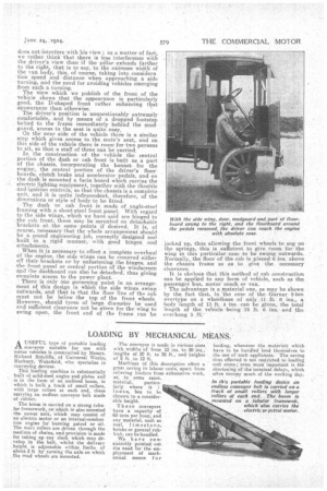
• There is only one governing 'point in an arrangement of this design in Which the side -Wings swing outwards, and that is that the floor line of the cab must not be below the top of the front wheels However, should tyres of large diameter be used and sufficient clearance not be given for the wing to swing open, the front end of the frame can be
jacked up, thus allowing the front wheels to sag on the springs, this is sufficient to give room for the wing 111 this particular case to be swung outwards. Normally, the floor of the cab is placed 6 ins, above the chassis frame so as to give the necessary clearance. It is obvious that this method of cab construction can be applied to any form of vehicle, such as the passenger bus, motor coach or van.
The advantage is a material one, as may be shown by the, fact that, in the case, of the Garner 2-ton overtype on a wheelbase of only 11 ft. 6 ins., a body length of 13 ft. 4 ins, can be given, the total length of the vehicle being 18 ft. 6 ins, and tho ovei hang 5 ft.