


A DESIGN FOR A BREAKDOWN LORRY.
Page 42
If you've noticed an error in this article please click here to report it so we can fix it.
A Résumé of Recently Published Patent Specifications.
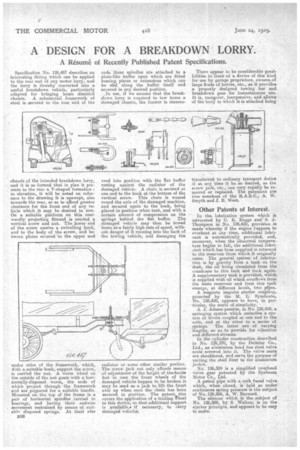
Specification No. 126,467 describes an interesting fitting which can be applied to the rear end of any motor lorry, and the lorry is thereby converted into a useful breakdown vehicle, particularly adapted for bringing home disabled chassis. A substantial framework of steel is secured to the rear end of the chassis of the intended breakdown lorry, and it is so formed that in plan it presents to the rear a. V-shaped formation : in elevation, it will be noted on reference to the drawing it is upswept, also towards the rear, so as to afford greater clearance for the front end of any vehicle which it may be desired to tow. On a suitable platform on this rearwardly projecting fitment is erected a vertical screw and nut. The lower end of the screw carries a swivelling hook, and to the body of the screw, and between plates secured to the upper and under sides of the framework, which, kith a suitable bush, support the screw, is carried the nut. A worm Wheel on the outside of the nut gears with a horizontally-disposed worm, the ends of which project through the framework and are prepared for a suitable handle. Mounted on the top of the frame is a pair of horizontal spindles carried in bearings, and having their endwise movement restrained by means of suitably disposed springs. At their r4ar B36 ends these spindles are attached to a plate-like buffer upon which are fitted bearing pieces or extensions which can be slid along the buffer itself and secured in any desired position. ,In use, if we assume that the breakdown lorry is required to tow home a damaged chassis, the former is reanceu vred into position with the Rat buffer resting against the radiator of the damaged vehicle. A chain is secured at one end to the hook at the bottom of the vertical screw. This chain is wound round the axle of the damaged machine, and secured again to the book, being placed in position when taut, and with a certain amount of compression on the springs behind the flat buffer. The damaged vehicle may then be towed home at a fairly high rate of speed, withont danger of it running into the back of the towing vehicle, and damaging the radiator or some other similar portion. The screw jack not only affords means of adjustment of the height of the /hook! but in case the front wheels of the damaged vehicle happen to be broken it may be used as a jack to lift the front axle up when once the chain has been secured in position. The patent also covers the application of a trailing heel to this device, so that additional support is available,i if necessary, to carry damaged vehicles.
There appear to be considerable possibilities its front of a device of this kind for use by garage proprietors, owners of large flsets of lorries, etc., as it provides a properly designed towing bar and breakdown gear for instantaneous use. It is, more...over, inexpensive, and allows of the lorry to which it is attached being•
transferred to ordinary transport duties if at any time it be so desired, as the screw jack, etc., can very rapidly be removed or replaced. The patentees are two members of the R.A.S.C., A. W. Smyth and J. B. West.
• Other Patents of Interest.
In the. lubrication system which is advocated by C. E. Beggs and S. J. Thompson in No. 126,4211, provision is made whereby if the engine bappens to overheat at, any time, additional lubricant is automatically provided, and, moreover, when the abnormal temperature begins to fall, the additional lubricant which has been supplied is returned to the reservoir from which it originally came. The general system of lubrication is by gravity from a tank on the dash, the oil being circulated from the crankcase to this tank and back again. A supplementary tank is provided, which is supplied with oil which overflows from the main reservoir and, from this tank emerge, at different levels, two prpes. A magneto impulse starter coupling, patented by the M. L. Syndicate, No. 126,426, appears to have, in particular, the merit of simplicity.
A. J. Adams patents, in No. 126,459, a springing system which embodies a system of levers coupled at one end to the axle, and at the other to a series of springs. The latter are of varying lengths, so as to provide for vibration and different stresses.
In the cylinder construction described in No. 126,370, by the Daimler Co., Ltd., an aluminium head has steel valve seats screwed into it. The valve seats are shouldered, and serve the purpose of uniting the steel liner to the aluminium jacket. No. 126,389 is a simplified overhead valve gear patented by the Sunbeam. Motor Co., Ltd.
A petrol pipe with a cork faced valve which, when dosed, is held so under continuous spring pressure is the subject of No. 126,506, A. W. Barnard.
The silencer which is the subject of No. 126,509, by S. Walton, is on the ejector principle, and appears to be easy to wake.