


Patents Completed.
Page 32
If you've noticed an error in this article please click here to report it so we can fix it.
Complete specifications of the following patents will be sent to any address in the United Kingdom upon receipt of eightpence per copy at the Sales Branch, Patent Office, Holborn, W.C.
ENGTNES.—Riley.—No. 23,390, dated 2nd November, 1908.—This invention relates to internal-combustion engines of the sleeve-valve type, and it has for its main object efficiently to cool the piston and the sliding sleeves. Instead of the piston reciprocating within the sleeves,
it slides in a stationary cylinder which is provided with a water jacket. The sleeve valves surround and slide on this cylinder, and surrounding the sleeves is another water jacket. Each of the sleeve valves is provided with a lip, and engaging this lip portion of the. sleeve is one arm of a bell-crank lever, the other arm of which is attached to connecting rods which are operated by eccentrics mounted on the half-time shaft.
CARBURETTER. Davis. — No.
15,528, dated 22nd July, 1908.—This carburetter is intended for use with heavy hydrocarbons such as paraffin, and it has for its object to regulate the supply of fuel and air according to the speed of the engine. A spindle which is driven from the engine extends through the carburetting chamber ; a governor is
mounted on this spindle. Within the carburetting chamber a fan is arranged, and this is mounted on a sleeve that surrounds the aforesaid spindle and is adapted to be driven thereby_ The fan is provided for the purpose of mixing the paraffin with the air. Also mounted on the spindle is a piston valve which controls the air inlet to the carburetting chamber. It will be seen that as the
speed of rotation of the spindle is increased the governors will cause it to move in an axial direction. This axial movement of the spindle causes the piston valve to cover the air inlets, and, at the same time, it closes the fuel inlet to the carburetting chamber. This is effected by means of a lever, one arm of which bears against the end of the spindle and the other arm bears against the fuel-inlet valve. A throttle valve is also connected to this lever by means of a link so that, as the engine speed increases, not only will the air and fuel inlet be regulated accordingly but also the throttle valve will be closed, NON-SKID DEVICES—Hamilton and Another.—No. 21,819, dated 15th October, 1908.—This invention relates to a non-skid device particularly applicable for use with twin tires. The device conaista of a number of segments that are disposed between the tires. These segments form a continuous band, but arc not connected together. A bolt attached to the segments is passed through the felloe of the wheel and secured to the other side by means of a nut. The form of the segments and their arrangement is such that the distortion of the tires, due to the weight upon them, forces the segments into contact with the surface of
the road. A spring is interposed between the nut and the felloe of the wheel to permit the segment to move in a lateral direction and to return it to its. initial position again. A rubber buffer is interposed between the segments and the felloe of the wheel.
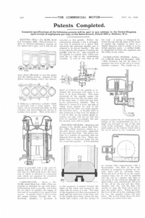
LUBRICATING SYSTEM.—Bollee.— No. 5,488/09, dated 3rd December, 1908. —This invention has for its object to maintain the level of the oil in a crank chamber constant. The cranks are at
ranged to splash the oil contained in the bottom of the crankchamber up into a small cup arranged on one of the side walls of the crankcase. This cup has a small orifice at the bottom which allows the oil to return to the crankcase, and
an opening that communicates with a floatehamber. The float in the floatchamber is arranged to operate an oilinlet valve and an oil-outlet valve. When the level of the oil in the crankchamber rises, the oil will be splashed into the cup at a greater rate than it can return to the crankcase through the small orifice, and, consermently, the level' of the oil in the cup and the floatchamber will rise, and the float will operate to close the inlet valve and to. open the outlet valve. When, however, the level of the oil in the crankcase sinks too low, the opposite action will take place. The second figure shows the float_ controlling an outlet valve only.