


The Control of Supercharged Engines
Page 62
If you've noticed an error in this article please click here to report it so we can fix it.
THE internal combustion engine has I the, inherent feature of giving a rising torque with speed, which is far from ideal for low-speed work and getting the vehicle under way. In these circumstances a steam-engine characteristic would be desirable, in which high torque is developed from a stand
still. An attempt to approach these conditions in an oil engine is shown in patent No. 692,198, which comes from A. Mueller and Leyland Motors Ltd., Suffolk House, Laurence Pountney Hill, London, E.C.4.
The patent refers to engines fitted with superchargers and deals particularly with a means for increasing the charge at low speeds yet limiting it to normal over the high-speed range.
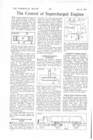
The drawing shows a diagrammatic layout of the proposed control mechanism. The engine (1) drives a supercharger (not shown) which can be driven at one of two speeds, high or low. The selecting mechanism is an electro-magnet (2) which, when energized, engages high gear.
The electro-magnet circuit can be broken at two points, one (3) being operated by the accelerator pedal and the other (4) being worked by a centrifugal governor. These switches ensure that the supercharger remains in low gear at high engine revolutions and at full-throttle pedal positions.
In other circumstances, high gear is engaged, but as fuel injection is controlled by the intake suction, some way must be found of artificially .lowering the suction so that extra fuel shall meet the extra air.
This is done by a pedal-operated bellerank (5) which opens a valve admitting air into port 6, whence it passes into pipe 7 leading to the pump controller (8). To prevent this unit from opening at high speeds, it, too, is electrically controlled, a magnet (9) acting as an obstruction when not energized. When it is energized, it does not open the valve but permits the bellcrank to do so only in the appropriate circumstances.
The actual supercharger and its electric control have been covered by earlier patents numbered 688,899 and 685,841.
REDUCING KNOCK AT PART LOADS • WHEN an oil engine is running under VY throttled conditions, such as at halfload or less, the reduction in the air charge often delays the moment of self-ignition and the engine knocks as s36 the result. To avoid this by simple means is the aim of a scheme shown in patent No. 692,927, by A. Sanders, Redinnick House, Penzance, Cornwall.
It is proposed to supply warmed air to the engine during part-load running, So that what the charge lacks in quantity is made up in heat value.
The drawing shows diagrammatically the arrangement, in which an extra-air pipe (1) is fitted to the intake, downstream of the throttle. The pipe draws its air from a jacket surrounding the exhaust pipe (2). The action is simple; at fujI throttle the hot-air pipe has little effect, but as the throttle is closed it supplies more and more heated air until, in the fully closed position, it forms the sole supply.
In actual practice the pipe is neatly enclosed in the manifold. The scheme is of no assistance for starting, but if desired an electric pre-heater can be provided for the purpose.
A HIGH-EFFICIENCY MAGNETO
PATENT No. 693,056 (J. Hempson and Ricardo and Co., Engineers (1927) Ltd., 21 Suffolk Street, London, S.W.1), shows the latest practice in magneto design. The scheme refers to
magnetos using stationary windings and rotary magnets made of one of the modern high-retentivity alloys.
These alloys are unmachineable except for grinding, and must therefore be cast nearly to the finished shape. The shape desired in this case is shown in the drawing, in which 1 is the rotary magnet and 2 the stator core. The required curved form is made up by soft-iron pole tips (3) which are fixed to the magnet by one of the high-strength thermosetting resins such as Araldite, After attachment, the pole tips can be machined to the curved form shown. A soft insert (4) is cast into the magnet to facilitate machining of the central hole. This construction not only helps in production, but the addition of iron tips gives certain important electrical advantages which result in increasing the output volts by as much as 40 per cent.
A GERMAN TANKER VEHICLE
GERMAN practice in the design of tanker vehicles is disclosed in patent No. 692,896, which comes from Fahrzeugbau Haller G.m.b.H., 150 Siemensstrasse, Feuerbach, Stuttgart. In such vehicles it is often required that the interior be divided into separate compartments, each of which can be separately emptied via its own conduit.
The patent is based on the use of these conduits as main constructional members, and states that a tank so made will need neither chassis frame nor cross-members.
The design is illustrated as applied to a semi-trailer. The tank in this case is divided into forward, middle and rear compartments, each of which has its own discharge valve (1). The three conduits (2) are of V-section and are used as chassis members, resting, respectively, on the rear axle and the turntable of the tractive unit.
Small triangular strengtheners (3) are attached at intervals in the length.
PISTON RING MANUFACTURE A CCORDING to patent No. 692,904, PA the standard method of manufacturing piston rings calls for eight or nine separate operations, the rings being handled many times. The patent describes a machine which, • when loaded with a casting, performs all the necessary work without being handled. The patentee is The Gabriel Company, Cleveland, Ohio, U.S.A.