


HINTS ON MAINTENANCE.
Page 30
If you've noticed an error in this article please click here to report it so we can fix it.
How to Get the Best Out of a Vehicle, to Secure Reliability and to Avoid Trouble.
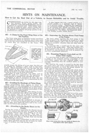
402 —A Clamp for the Front Wing Stays of the the Peerless.
The front wing stays of Peerless lorries sometimes break under the effects of vibration, and in nine cases out of ten this occurs across the bolt holes of the lugs by which they are attached to the frame. This usually means the fitting of a new stay, but this can be avoided by utilizing a plate such aio-thataillustrated. This is intended to fit over the stay lug, and when bolted tei the chassis it forms an excellent clamp which.holds the front wing in position, even if the lug be broken at all three bolt-holes.
The ,plate is made from kin. iron plate, and no elaborate tools are required for the operation, it being possilale to punch holes through the metal. Sometimes it Will be necessary to make, the slot larger than that shown, but this is determined by the
thickness of the stay itself.
403.—Avoiding the Breakage of Piston Rings.
When reassembling those engines in which the ylinder heads are not detachable it is -sometimes a difficult matter to avoid breaking one or more piston rings while replacing the cylinders, particularly if this job has to be done single-handed.
In order to avoid the difficulty, after fitting the big ends to the crankshaft take off the caps and lay them in their correct order on a board or table. Now insert the pistons, complete with rings and-connecting rods,. into their respective cylinders, and lower the cylinder block on, tp the crankcase.
We will assume that the crankshaft is already in position. It will now be found quite easy to refit the big-end caps, after which the lower half of the crankcase can be bolted into position.
404.—Attending to the Brake Shoes on the Dennis.
During the course of inspecting the Dennis chassis it may be noticed that the pins on which the handbrake shoes fulcrum have been getting no oil and, consequently, cause stiff' working. This may be traced to the oil-holes in the top of the shoes having become filled with dirt orthrough their not having been attended to regularly. It is advisable, when overhauling, to take down the brake shoes and drill and tap the oil holes for lubricators of medium size with spring caps. 544
40.5.—Improving the Friction-driven Feed Pump of the Foden.
The lever which 'operates the feed pump of the Poden is heldin the off position by means of a small catch, which engages with a slot on the gauge plate. Owing to excessive vibration this slot may, wear at the -bottom.
To overcome this, a sniall rest for the catch may be fitted to the gauge plate. This rest consists of a piece of metal 2 ins. by 1 in. and of i-in. steel plate. It should be case-hardened and held in position. by two g-in. countersunk setscrews. -
406.—Repairing Magneto Cross-shaft on J.B. 4-type Tyler engine.
In a previous hint we gave one method of effecting a repair to the magneto driving cross-shaft of the Tylor engine, but this, required rather more -accurate machining than the method which we now eescribe.
The need for the repair is caused by -the fact that the pump drive end wears -considerably and it then 'becomes impossible to• keep' the' pump spindle in mesh with the dog of the cross-shaft.
In order to avoid having' to renew the whole shaft, the worn end should be cut off and the shaft -set nilin the chuck of a lathe, being Set true with the teeth of the wheel and the hearings of the shaft. Now drill 'the end from which the piece has been cut off to a depth of 11 ins., screwing the whole fin. left-hand 16 threads per inch. It is advisable before doing this to recess the bottom of the hole in order to allow the screwing tool to start. A left-hand thread is utilized, as 'otherwise, the new end would tend to unscrew itself when engaged with the pump. -The new dog .ean be turned from a piece of good -mild steel, leaving sufficient on the outside to allow this to be skimmed over after the dog is screwed into position. A small groove should be cut -across the threads for the whole length to permit the escape of air when the dog.is screwed home.
Now, after skimming the dog until it is of the same idiameter as the shaft and cutting the necessary groove for the dog on the pump spindle, the new end may be removed, case-hardened, a-nd refitted.