


EQUIPPING A COACH FOR WIRELESS RECEPTION.
Page 14
Page 15
If you've noticed an error in this article please click here to report it so we can fix it.
A Simple and Clear Explanation of Sound Amplification by Means of Transformers. The Analogy of the Magneto.
IN THE article which appeared in last week's issue of The Commercial Motor (being the third of the present series dealing with the details ofthe sound-amplifying instrument itself---=the preVious series having dealt with the aerial and earth equipment), we outlined the uses of valves as amplifiers, and also pointed out the fundamental requirements to be. observed in coupling two valves together. Iu this article we will now discuss the various circuits that can be employed in amplifiers, and, since it will he a bit easier to understand, we will take low-fre.quency amplification, or, as it is more generally railed, note magnification, first, . Note magnification is earried out -by; magnifying the audio-frequency, Or 'Speech ' frequeney, currents that result: after reetificationi has been carried out. Stiiertly 'SPeaking, theft, it has 'nothing to do with radio proper and the apparatus with which we carry it out should be just as applicable to an Ordinary land telephone as to a radio 'phone. This is, indeed, the
case. . . . .
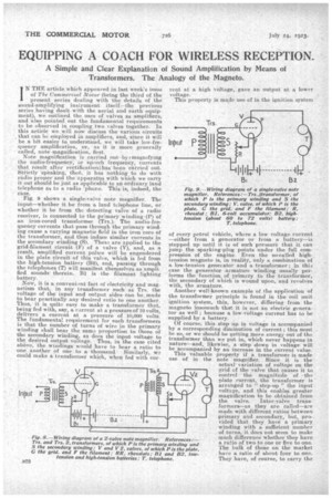
.E'ig. 9 shows a single-valve note magnifier. The input—whether it be from a land telephone line, or whether it be from the detecting valve of a radio receiver, is connected to the primary winding(P) of an iron-cored transformer (Trs.). The audio-frequency currents that pass through the primary winding cause a varying magnetic field in the iron core of the transforniert and thus induce similar currents in the secondary winding (5). Thes., are applied to the grid-filament circuit (F) of a. valve (V), and, as a result, amplified current pulses will be engendered in the plate circuit of this valve, which is fed from the high-tension battery (B), and, passing through the telephones (T) will manifest themselves as amplified sounds.therein. B1 is the filament lighting
battery. _
.Now, it is a convenient fact of electricity and magnetism that, in any transformer such as Trs. the voltage of the input and output sides can be,made to bear pyactically any desired ratio to one another. Thus, it is quite easy to make a transformer that, being fed with, say, a earrent at a pressure of 10 volts, delivers a current at a pressure of 10,000 volts. The fundamental requirement for such transformers is that the number of turns of wire in the primary winding shall bear the same proportion to those of the secondary winding, as does the input voltage to the desired output voltage. Thus, in the case cited above, the windings would have to bear a ratio to one another of one to a thousand. Similarly, we could make a transformer which, when fed with cur
rent at a high voltage, . gave an output at .4 lower voltage. This property is made use of in the ignition system
of every, petrol vehicle, where a low voltage current —either from a generator or from a. battery—is stepped up until it is of such pressure that it can jump the. sparking-plug points under the full compression of the engine Even the so-called hightension magneto is, in reality, only a combination of a low-tension generator and a transformer ; in this case the generator -armature winding usually performs the function, of primary to the transformer, the secondary of which is wound upon, and revolves with, the armature. Another well-known example of the application of the transformer principle is found, in the coil unit ignition system, this, however, differing from the magneto insomuchthat it is not an electric generator as 'well; because a low-Valtage current has to be supplied by a. battery.
Of course; this step hp in voltage is accompanied by a corresponding diminution of current ; this must be so, or we should be getting more energy out of the transformer than we put in, which never happens in nathreand, likewise, a step-down in voltage will be accompanied by an increase in the earrent value. This valuable property if a transformer, is made u•se of in the note magnifier. Since it is the actual. variation of voltage on the grid of the .valve that causes it to control the magnitude of the plate current, the transformer is arranged to " step-up " the input voltage, and this enables greater magnification to be obtained from the valve. Inter-valve transformers—as they are called—are made with different ratios. between primary and secondary, but, provided that they have a primary winding with a sufficient number of turns, it does not seem -to make much difference whether they have a ratio of two to one or five to one. The bulk of these on the market have a ratio of about four to one. They have, of course, to carry the :full plate voltage on the input side, so that they need to hie specially carefully constructed and insulated, which-means that a retiable• inter-valve transfeirrner is relatively expensive. This, however, is one of the, 'places where it most certainlydoes not pay to 'buy cheap and inferior goods, and the higher prices 'asked for reputable makes are worth paying.
Fig. 9 shows another stage of note magnification -added to the first. it will be.noted that .it is only .necessary to replace the telephones (T) irs Fig. S. by the primary of another inter-valve. transformer (Trs.2) and insert the 'phones in the plate circuit of the valve (V2). A third stage can be added if desired in exactly the same way. it is -not, as a rule, however, desirable to go beyond three stages of note magnification, and it is better 1,6 confine oneself to two. This is because each transformer introduces .a little distortion, which is magni fled by the. valve. following, along with the speech and eikft stage is capable of some -seven-. fold magnification, it will be seen that the distortion will,after two or three stages, become so serious as to prevent further magnification of the signals. MoreOver, inter-valve transformers will readily pick up .straY magnetic/ fields, and, therefore, however carefully the magneto is screened, trouble from this soniee is bound to occur if too Much note magnificatiOn is indulged in. Where more volume of sound is required--such as for operating 'loud speakers—than is given by two stages of note magnification and ordinary valves it is far better, to have recourse to power valves and -higher plate voltages. A. oumber of these .are on the market, and will be described when we come to consider the various types of valVes and their uses. ,',:incidentally, it may be stated that t-aives are being rapidly developed.