


Patents Completed.
Page 72
If you've noticed an error in this article please click here to report it so we can fix it.
Complete specifications of the following patents will be sent to any address in the United Kingdom. by the Sale Branch, Patent Office, Holborn, W.C., upon receipt of eightpence per copy.
An Electric Start 1,. W. Lanchester, No. 12,418, dated 25th May, 1912.—The accompanying drawing shows the method oNnounting, on a motor vehicle, a dynamo which is used as a motor for starting the engine and as a generator for other purposes. A
bridge is provided across the dumb-irons or the chassis members in front of the radiator, and the dynamo, with an epicyclic variable speed gear, is carried on it. Preferably a smallldynamo is used running at a high speed and two sets of epicyclic gears are used in tandem, each having a reduction of 4 or 5 to 1, giving a total reduction of about 20 to 1. If desired a very small machine may be used running at a very high speed and three sets of gear used in tandem. The specification describes and illustrates a particular construction of epicyclic gear which is suitable, and also a flexible coupling which is provided between the dynamo and the engine.
Improved Springing System.
The Wolsclity Tool and Motor Car Co., Ltd., and A. A. Remington, No. 17,101, dated 23rd July, 1912.—This invention relates to means for supporting the body of a motor vehicle from the front axle in such a way that, while it preserves the quickness of periodicity which is re quin-d in the :piing sesaension 'India. the v:aaisal movements of both the front wheels simultaneously, it allows either cf
these wheels to rise independently of the other, as when one wheel is passing over an obstacle, with much less tendency to tilt, or even distort tho frame, than with ordinary methods of suspension. This is accomplished by providing the front axle with three springs, one each side of the vehicle frame as is usual and one between the frame and the middle point of the axle ; this spring can be of any suitable form and is preferably of a quicker periodicity than either uf the side springs, and it is arranged so that the axle can tilt freely. When both front wheels rise together all sorin4s yield and thus the periodicity results from the full action of the three springs, but when only one wheel rises the middle spring yields only half the amount it. would if both wheels rose together, and the spring on the same side as the rising wheel yields considerably ; the relative periodicity between the axle and the frame is slower under this condition than when. both wheels rise together.
. An Improved Radiator, J. W. Roebuck, No, 14,440, dated 20th June, 1912.—This invention consists of an improved construction of radiator in
which all the joints are mechtudeally made, so dispensing with all soldered work; thus the complete radiator can be assembled and taken to pieces when required and is consequently easy to repair; parts can also be readily replaced. Each header is made with one side stepped in, the vertical side of this step being machined and packing which fits the stepped-in portion interposed between it and the water tank, conununivathin being made between the header and the tank. The cooling tubes, which may be arranged in groups, communicate with the tanks at. the top and bottom of the radiator in the usual manner. These tubes are fitted into the tanks by means of special resilient packing.
A Paraffin Carburetter.
M. E. Caudwell, No. 1835, dated 22nd January, 1913.—This inveution elates to carburetters for using paraffin or other heavy oils requiring to be vaporized before use in internal-combustion engines; it also provides an adjust
able automatic throttle having gas and air ports, by the action of which the gas and air are automatically mixed in the throttle in correct proportions before passing to the engine. The vaporizer is bolted together around the exhaust pipe to form a chamber; it is provided with an internal helix and fits tightly around the exhaust pipe, forming a channel of increasing sectional area from the oil inlet to the outlet.. The oil in passing through this channel is vaporized and is free to expand owing to the increasing size of the channel. The vaporized oil then passes to the adjustable throttle and air-mixing chamber and thence to the engine Truing-up Valves.
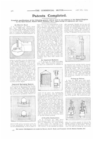
Noel, No. 8979, dated 16th April, 1913.—The accompanying drawings show a useful tool for refacing valves and valve scats. It consists of a suitable holder which is screwed into the valve easing, and has a central screw-threaded socket to receive a spindle which, in the one case, has a suitably coned emery wheel mounted on tine lower end. This spindla is driven by a hand-wheel having teeth to engage a long narrow pinion at tht, top of the spindle. The construction per
mits of a certain amount of feed of the spindle without re-setting the position of the hand-wired on the socket. In this way it is used for facing up valve seats.