


Starter motors, 4
Page 50
If you've noticed an error in this article please click here to report it so we can fix it.
■ IERTIA type starter motor rives described in the last artie are not suitable for the larger etrol engines and diesel enines.
The greater torque required to :art them involves the use of a rger starter motor, and the moientum built up by the larger -mature as engagement of the inion with the flywheel teeth rkes place imposes a consider)le shock and damage is likely. In the case of diesel engines, le high pressure on the piston imediately after the compreson stroke accelerates the pisIn downwards so rapidly that e pinion of the inertia-type -ive is likely to be thrown out of -igagement.
To overcome these difficulties ere are starter motors in which e pinion engages with the (wheel ring gear before the arter begins to rotate.
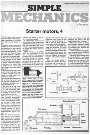
Several different methods are ;ed to slide the pinion into esh with the flywheel teeth. It ay be done manually or by a ilenoid (see Figure 1).
In this type, when the driver :esses the starter switch, a cu rnt of low amperage flows ound the solenoid draw-pin il carrying a plunger filluslted) to move to the right. This plunger movement o yes a pivoted engagement rer to shift the pinion to the left that it engages with the fly'eel ring gear. Further moveent causes the magnetic (itch to close, completing the am n starter motor circuit so that • starter revolves. As the pi n is already in mesh with the wheel teeth the engine is ro:ed.
When the driver releases the arter switch, the solenoid anger returns to its original sition, withdrawing the pinion im the flywheel and braking main starter motor circuit.
4n over-run clutch or free ;eel is fitted so that in the ent of the driver not releasing starter switch, the starter motor is not driven by the engine at excessive speed.
In another type, instead of the pinion sliding into engagement with the flywheel teeth, as in the type just described, the whole armature assembly slides axially to engage the pinion with the flywheel.
Figure 2 shows in simplified form the construction of this type of machine. The starter is shown at rest, the armature being held to the right by a spring. The solenoid has two pairs of contacts, the first pair are brought into contact when the starter switch on the dash is first
operated, the second pair are prevented from closing at this stage by a pawl engaging in a slot on the trip lever until the pinion is almost fully engaged.
The motor is provided with three field windings. The main winding is the usual heavy winding connected in series with the armature. The second and third windings have thinner wire and their purpose is to pull the armature to the left and to hold it there.
When the starter switch is pressed the second and third windings are energised, the armature rotates relatively slowly and slides to the left, bringing the pinion into engagement with the flywheel.
When the pinion is almost fully engaged, the pawl releases the trip lever and the second pair of contacts in the solenoid are allowed to close.
Current now flows through the main winding and the starter becomes fully operative.
The pinion is connected to the armature shaft by a multi-plate clutch, not shown in the sketch, to protect the starter from damage if the engine backfires or if the engine starts and drives the motor at an excessive speed.