


Coil-spring Rear Suspension for Rigid Axle
Page 34
If you've noticed an error in this article please click here to report it so we can fix it.
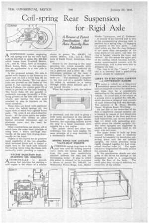
A Resume' of Patent Specifications that Have Recently Been Published
ASUSPENSION system emploYing coil springs and for use with rigid axles isdescribed in patent No. 529,948 which comes from Vauxhall Motors, Ltd., and M. 01ley, both of Kirnpton Road, Luton,. Beds. In the specification an. application to a rear axle is described.
In the proposed scheme, the axle is guided with respect to the frame by an upper link (1) and a lower link (3) on each side of the chassis. The two upper links are pivoted on the frame at the points 5, but converge rearwardly to form a V-shape, the central point (2) of which is pivoted on the axle housing. The lower links {3) are parallel or preferably converge forwardly a little, being pivoted on the axle tube near the wheels, and having the front ends attached by pins to brackets on the frame members.
These links are fitted with platforms to carry the helical springs (4), the upper ends of which bear against frame pads. The arms 6 are shock-absorber levers. All the pivot points are preferably bushed with rubber to allow limited .universal movement and to eliminate, noise and the need for lubrication.
Other constructions are shown, all of which have the same basic principle of using links 1 which converge rearwardly, at the same time sloping downwardly at the front.
Objects of the layout are to preserve equal angularity of the two propellerShaft universal joints and to impart a slight turn to the back axle towards the turning centre when the frame rolls outwardly while rounding a corner,
-EXCESS INJECTION FOR STARTING OIL ENGINES A, UTOMATICALLY to provide ,r1 excess fuel injection for starting a cold engine is the object of a scheme
shown in patent No. 529,671, by Albion Motors, Ltd., •and E. Stead, both of South Street, Sootstoun, Glasgow.
Shown in the drawing is the usual governor (4), which normally shifts the position of the pump rack-rod (2) via a push-rod and a lever (3). The full-output position of the rack is determined by its striking an abutment (1). The abutment is attached to the free end of a metallic bellows (5) which is enclosed in a casing through which flows exhaust gas, cr air heated thereby.
When the engine is cold, the bellows is shortened, and the rack is given a little extra movement in the full-output direction. As the engine warms, however, the expanding bellows moves the stop to a lesser maximum MOTE suitable for a hot engine.
The patent shows two other constructions, but they both employ the same principle of a stop movable by a thermostatic device. 4 SPRING RINGS FOR LOCKING VALVE-SEAT INSERTS
ALTHOUGH spring rings have in the past been used for locking inserted valve seats, the system has suffered from the poor heat cOnductivity afforded between the seat and the surrounding metal. A plan in which this defect is claimed to be overcome is shown in patent No. 529,511, by Wellworthy Piston Rings, Ltd., Radial
Works, Lymington, and C. Grahame. A section of an inserted seat is seen in the accompanying drawing, held in position by a spring ring (1) engaging
in grooves in the 'two parts. The chief points are that the ring thickness is not more than one-quarter of the total depth of the insert, and that the ring is located towards the lower end thereof. By this means the upper part of the seating, which becomes hottest, makes uninterrupted contact with its surroundings, and is,thus 'more 'able to dissipate the heat.
The ring is of the " wavy " type, and it is essential that a, good-fitting groove should be employed. • LORRY TO STRETCHER CARRIER —A CONVERSION SCHEME
equip a vehicle as a ternporary elambulance means that racks of some sort are required to carry the stretchers, and these may be a considerable obstruction to the normal duties of the vehicle. To avoid this is the object of a scheme shown in patent No. 529,384, which discloses a design of rack capable of rapid dismantling and easy stowage. The patentee is R. Benn, Norfolk House, Brighton Road, Worthing.
On one side of the centre-line of the floor a lengthwise channel member (3) is located by means of two dowel-pins inserted in holes in the, floor and front wall respectively, and carries welded-on lugs (4) fitted with upstanding pins, which locate the tubular uprights (2). The other uprights are supported in sockets (5) permanently fixed to. the body side and front.
The upper frame is built up from channel members, and is similarly located for assembly by dowel-pins projecting down into the six tubular uprights, the whole structure being rigidly clamped together by four wing'nutted strainer bolts (1). The upper and lower longitudinal channels receive the stretcher legs.
In the specification details are also given of the means for stowage of the dismantled parts in a compartment under the floor of the body. The small space they occupy is definitely an attraction of the scheme.