


THE UPKEEP OF STEAM WAGONS.
Page 14
Page 15
Page 16
If you've noticed an error in this article please click here to report it so we can fix it.
No. 11.—Engine Overhaul and Repairs.
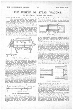
THE FIRST PARTSrequiring attention on the engine are the cylinders. The barrels and the valve faces will be worn and need truing. Usually the wear in the barrels is compensated by fitting larger piston rings, "but; as the wear takes place principally on the bottom, causing them to become oval, this is not always a *satisfactory job and the cylinders require re-boring.
This can be done without taking the cylinders off the boiler by using a portable boring machine, as is illustrated in Fig. 33. A is the boring bar with sliding cutter head (B), carried in two dummy flanges (0 and D) bolted on each end of the cylinder. The flange (C) carries the worm gear operated by the hand wheel (E), for driving the boring bar. A feed screw (F) is fitted to the bar for traversing the cutting head (B), the feed being obtained by the star wheel engaging catch (H) every revolution. Three cutting tools (J) should be fitted to the head, and these must be adjusted to give the proper finished diameter. When rigging up the tackle, first insert a pointer in one of the tool holes in cutting head, and traverse it through the barrel, testing -With feelers to ascertain if the bar is set centrally and also to what size the barrel should be re-bored. Take out as little as possible—just sufficient to clean it up. Then adjust the cutters to give the required diameter and bore through the barrel, testing the bore with a sliding bar gauge such as is shown in Fig. 341 Two sets of dummy flanges and cutting heads will be required to suit the high-pressure and low-pressure barrels. The simplest way in which to reface the slide and stop valve faces is to use a 'block file as shown in Fig. 35: With this tool, the scores and hollows can be filed out, and the-faces afterwards scraped up, using a -small surface plate for testing. A portable milling machine for slide valve faces can be Obtained
from Messrs. W. H.' Willcox and Co., London, or Messrs. Hodges Bros., Ltd., Exeter. The valves can be filed and scraped up to a surface plate in the ordinary way, but if they are worn too thin, new valves should be fitted, for there is a danger of the B36 port in the valve becoming too shallow and restricting the passage of steam. In all probability, the holes in the glands and bosses will be worn too large and oval by the spindles.
If so, small bushes should be fitted as shown in Fig. 36, the holes (D) being made smaller in diameter to suit the valve spindles after they have been trued up.
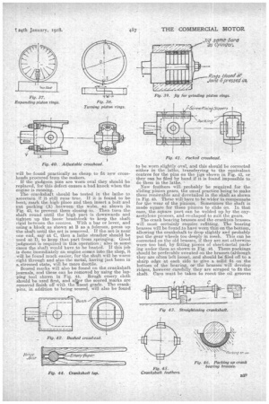
If the cylinder barrels or the piston grooves are not worn too much it is quite possible that the pjston rings can be used again by expanding them. Place the rings on a smooth block of iron and hammer them all round on the inside with a reund-nosed hammer, as shown in Fig. 37. The blows must be heaviest at A, and decrease in force each side towards the joint. 'This will open out the rings and they should be tried in the cylinder until -sufficient expansion has been obtained.
To make new rings, procure a east-iron .eylinder about' I in. larger in diameter than the bore of the cylinder, turn and. bore to the sizes shown in Fig. 38. Now cut off the rings about 1-32 in. wider than the grooves in the piston and grind on the sides to finished size. Then cut out the parts (W). The rings should now be pressed into a jig and clipped on a mandril,' as shown in Fig. 39; the jig removed and the rings ground on the outside to the finished size. Some makers fit special types of piston rings such as
Buckley or Lancaster, and, in this case, new rings must be procured from the makers. , The piston rods can be trued up by drawfiling and smoothing if they are not badly worn ; but if too bad they should be trued up in the lathe, taking off as little as possible. New cotters for the cross-head end will probably be needed, and the cross-head slippers lined up to adjust for wear. • •
Some cross-heads are Made adjustable to allow for wear, as shown in Fig. 40, which only require a reduction of the packing (X) and tightening up of the nuts (Y), to-: increase the diameter ever the slippers. Others.are made as shown in Fig. 41, which reouire liners under the slippers to take up the wear. With the typen shown in Fig. 42 the cross-head can be turned down and a bush fitted on the outside ; but it will be found practically as cheap. to fit new crossheads procured from the makers.
if the gudgeon pins are worn oval they should be replaced, for this defect causes a bad knock when the engine is running.
The crankshaft should be tested in the lathe to ascertain if it still runs true. • If it is found to be bent, mark the. high place and then insert a bolt and nut packing (A) between, the webs, as shown in Fig. 43, to prevent them closing in. Then turn the shaft round until the high part is downwards and tighten up the loose headstock to keep the shaft rigid between the centres. With a bar or lever, and using a block as shown at B as a. fulcrum, press up the :shaft until the set is removed. If the set is near one end, say at C, then a lathe steadier should be used at D, to keep that part from springing.. Good judgment is required in this operation ; also in some.. cases the shaft would have to be heated. If this job is done immediately an engine conies into. the shop, it will be found much easier, for the shaft will be warm right through and also the metal, having just been in a, stressed state, will be more ductile.
Scored marks will also be found on the crankshaft journals, and these can be removed by using the lapping tool shown in Fig. 44. Rough emery cloth . should be used first, and at ter the scored marks are removed finish off with the 'finest grade. The crankpins, in addition to being scored, will also be found to be worn slightly val, and this should be corrected either in the lathe, transferring to the equivalent centres for the pins on the jigs shown in Fig. 43, or they can be filed by hand if it is found impossible to do them in the lathe.
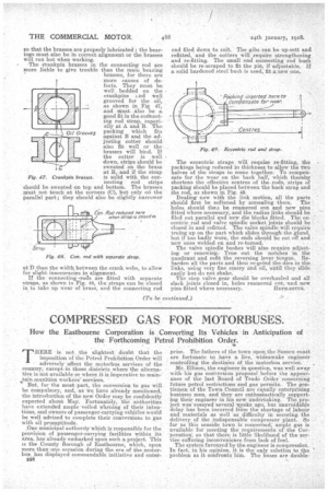
New feathers will probably be required for the sliding_ pinion gears, the usual practice being to make these renewable and dovetailed in the shaft as shown in Fig. 45. These will have to be wider to compensate for the wear of the pinions. Sometimes the shaft is made square for these pinions to slide on. In that case, the square part can be welded up by the exyacetylene process, and re-shaped to suit thegears. The 'crank hearing brasses and the crankpin, brasses will most certainly require refitting. The bearing brasses will be found.to have worn thin on the bottom, allowing the crankshaft to drop slightly and probably put. the gear wheels too deeply in mesh. This can be corrected on the old brasses, if they are not otherwise worn too bad, by fitting pieces of sheet-metal packsing under them as shown in Fig. 48. These packings should be preferably sweated on the brasses (although they are often left loose), and should be, filed off to a sharp edge at each side to give a solid fit on the bottom of the bearing, or the brasses will develop ridges, however carefully they are scraped to fit the shaft. Care mast be taken to recut the oil .grooves so that the brasses are properly lubricated • the bearings must also be in correct alignment or die brasses will run hot when working. The c`rankpin brasses in the connecting rod are more liable to give trouble than the 1118,11i bearing brasses, for there are more causes of defects. They must be well bedded on the 'crankpins and *ell grooved for the oil, as shown in Fig 47, and must also be a good fit in the cotibecting rod strap, especially at A and B. The packing which fits against B and the adjusting cotter should also fit well or the brasses will bind. If the cotter is well down, strips should be sweated on the brass at B, and if the strap
Fig. 47. Crankpin brasses. is solid with the connecting rod strips should be sweated on top and bottom. The brasses must not touch at the corners (0), but only on the parallel part; they should also be slightly narrower
at I) than the width between the crank webs, to allow for slight inaccuracies in alignment. • If the connecting -rods are fitted with separate straps, as shown in Fig. 48, the straps can be closed in to take up wear of brass, and the connecting rod
end filed down to suit. The gibs can be up-sett and refitted, and the cotters will require strengthening and -re-fitting. The small end connecting rod hush should be re-scraped to fit the pin, if adjustable. If a solid hardened steel bush is used, fit a new one.
The eccentric straps will require re-fitting, the packings being reduced in thickness to allow the two halves of the straps to come together. To compensate for the wear on the back half, which thereby shortens the effective centres of the rods, strips of packing should be placed between the back strap and the rod, as shown m Fig. 49.
Dealing now with the link motion, all the parts should first be softened by annealing them. The holes should thea be reamered out and new pins fitted where neees.sary, and the radius links should be filed out parallel and new die blocks fitted. The eacentric rod and-valve spindle soCket joints should be closed in and refitted. The valve spindle will require truing up on the part which slides through the gland, hut if too badly worn, the ends should be cut off and new 'ones welded on and re-turned.'
. The valve spindle bushes will also require adjusting or renewing.. True out the notches in the quadrant and refit the reversing lever tongue. Reharden all the parts and than re-grind the dies in the .links, using very fine emery and oil, until they slide easily but do not shake. .
The stop valve gear should be overhauled and all slack joints .closed in, holes reameresi Cut, .rid. new
pins fitted where necessary. HEPRZESTUS.