


• COMPRESSED GAS FOR LORRIES.
Page 12
Page 13
If you've noticed an error in this article please click here to report it so we can fix it.
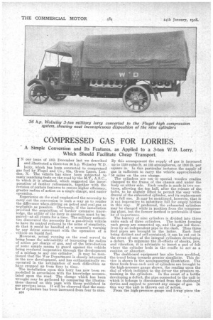
A Simple Conversion and Itsl Features, as Applied to a 3-ton W.D. Lorry, Which Should Facilitate Cheap Transport.
IN our issue of 13th December last we described and illustrated a three-ton 36 h.p. Wolseley W.D. lorry, which has been convertedto compreised gas fuel by Flugel and CO.,. 33a, Green Lanes, London, N. The vehicle has since been subjected to many searching tests on the road by the M. L, A.S.O., to which it is attached, which suggested the incorporation of further refinements, together with the revision of certain features to ensure higher efficiency, greater radius of action on a single charge, and easier
operation. .
Experience on the road emphasized the necessity to carry out the conversion ;n such a way as to render the difference when. driving on petrol and coal-gas as negligible as possible. Obviously, if the installation involved the acquisition of further extensive knowledge, the utility of the lorry in question 'must be impaired—at all events for a time. The military authorities discovered the necessity for a gas-driven vehicle to have its control reduced to the acme of simplicity, Fro that it could be handled at a moment's warning by any driver conversant with the operation of a , vehicle on liquid fuel. Moreover, actual running on the road served to bring home the advisability of increasing the radius of action per charge of gas, and of the introduction of some simple means to guard against the vehicle being rendered inoperative through the development of a mishap to any one cylinder. It may be mentioned that ihe War Department is closely interested in the new development, and has enthusiastically cooperated in the subjugation of such difficulties as have cropped up from time to time.
The installation upon this lorry has now been remodelled in accordance with the knowledge accumulated upon the road. The change which has been wrought may be gathered by comparing the illustrations thereof on this page with those published in our previous issue. It will be observed that the number of cylinders has been increased from four to nine.
B34 By this arrangement the supply of gas is increased up to 1350 cubic ft. at 125 atmospheres, or 1800 lb. per square in. In this particular' instance the supply of gas is sufficient to carry the vehicle approximately 56 miles on the one charge.
The cylinders are -aet-inspecial wooden cradles clamped -to the frame of the chassis .and under, the body on either side. Each cradle is made in two sections, allowing the top half, after the release of the bolts, to be slightly, lifted to permit the easy withdra,wal of the 'exhausted Cylinder, and-its replacement by a full one. It may be mentioned, however, that it is not imperative to. subStitute full.for erripty bottles in this' way. If preferred, the exhausted cylinders may be charged while in position from the compressing plant, but the former method is preferable if-time be of importance. The battery of nine cylinders is divided into three units each of three cylinders. The bottles forming each group are connected up, and the gas led therefrom by an independent pipe to the dash. Thus three feed pipes are brought. to the latter. Each feed being distinct and self-contained, it can be cut out in the event of one of the integral cylinders developing a defect. To minimize the ill-effects of shocks, jars, and vibration, it is advisable to insert a pad of felt where the cylinder beds in the cradle to act, as a cushion or absorber.
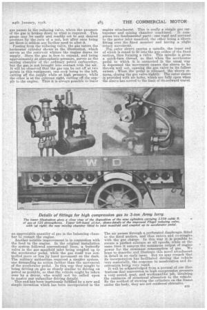
The dashboard equipment has also been modified, the trend being towards greater simplicity. This device is shown in the accompanying illustration. The three feeds from each unit of cylinders are brought to the high-pressure gauge shown, the reading upon the dial of which indicates to the driver the pressure remaining in the cylinders. In the event of a bottle developing a defect, the pipe connected to the unit to which it belongs is disconnected from the dashboard device and capped to prevent any escape of gas. In this way 'the unit is thrown out of action. From the high-pressure gauge and 5-way' piece the
gas passes to the reducing valve, where the pressure of the gas is broken down to what is required. This gauge may be easily and readily set to. any desired pressure by the turn of a nut, but after once being set there is seldom any further need to alter it.
Passing from the reducing valve, the gas enters the _horizontal cylinder shown in the illustration which serves as the reservoir whence the engine draws its supply. Here the gas is free, to expand, and being approximately at atmospheric pressure, serves as the mixing chamber of the ordinary petrol carburetter, but the gas is not brought into contact with the air. It will be observed that the gas can be cut off at two points in this .equipment, one cock being to the left, cutting off the supply while at high pressure, while the other is at the extreme right, cutting off the supply to the engine. Thus it is always possible to leave
an appreciable quantity of gas in the balancing chamber to restart the engine. Another notable improvement, is in connection with the feed to the engine. In the original installation the system followed conventional lines, a butterfly valve in the gas manifold inlet being coupled up to the accelerator pedal, while the gas itself was controlled more or less .by hand movement on the dash. The military authorities required a simpler system, one demanding no action further than the movement of the accelerator pedal. In this way they sought to bring driving on gas as closely similar to driving on petrol as possible, so that the vehicle might be taken over by a driver, who would not be called upon to master any unfamiliar driving details': This end has been ingeniously fulfilled by a new and simple invention which has been incorporated in the engine attachment. This is really a simple gas carburetter and mixing chamber combined. It comprises two fundamental parts—one rigid and screwed to the motor inlet manifold, the other being a sleeve fitting over the fixed member and having a slight rotary movernent. The outer sleeve carries a spindle, the inner end of which is coned to fit into the gas orifice of the fixed section, thus forming a valve. This spindle is given a quick-turn thread, so that when the accelerator pedal to which it is connected in the usual way is depressed the movement causes the sleeve to be thrown well out, opening the gas valve to its fullest extent. When the pedal is released, the sleeve returns, closing the as valve tightly. The outer sleeve is provided with air holes, which are fully open when the sleeve has moved to the limit of its outward travel.
The air passes through a perforated diaphragm fitted Le the fiXed section, and thus entern and co-mingles with the gas cha:rge. In this way it is possible. to secure a perfect mixture at all speeds, while at the same time it assures the maximum output of engine power for the minimum consumption of gas. We hope to describe and illustrate this novel attachment in detail in an early issue. But we may remark that its incorporation hasfacilitated driving the vehicle very materially, the response to acceleration and deeeleratiOn being very rapid. It will be acknowledged from a perusal of our illustrations that conversion to high compression presents a very sound, neat, and workmanlike job, involving the minimum of structural alteration to the vehicle. By the method of stowing the cylinders on the frame under the body, they are not rendered obtrusive.