


Tractor Spuds That Follow Tyre Flexure
Page 32
If you've noticed an error in this article please click here to report it so we can fix it.
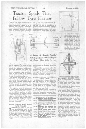
LARGELARGELY to relieve tractor spuds or LY of driving stresses is the object of patent No. 516,007 by D. N. /deHardy, of Glengariff, Wellington Avenue, Hatch End, Middlesex. The design is primarily intended for application to pneumatic-tyred agricultural tractors.
From the drawing it will be Doted that the strakes (1) are hinged to arms (2) and, although their movement is limited, they can move, in relation to the wheel, with the tyre tread (3). Thus, when a spud is on the ground, the tyre rests upon it and accordingly much of the traction is by friction between tread and metal instead of through the spud mounting gear.
The strakes and arms are easily detachable, a single handle-operated nut securing their inner ends at the centre of the wheel and tapered sockets gripping them near the wheel-rim (4'. Provision is made for dislodging each arm from the latter fixing by a hammer blow.
One suggested means for attachment of the articulated strain incorporates a hinge pin, provided with a tommybar, by which the spud can be pulled. axially in respect of the pin, against a spring, for a sufficient distance to disengage a simple form of dog clutch which retains the spud whilst permitting the necessary freedom of articulation, in the " in-action " or " outof-action " positions.
PETROL ENGINE WITH THIRD VALVE FOR AIR
ASCAVENGING blast of pure air from an additional valve is the chief feature of a design of petrol engine shown in patent No. 515,697 by B. Read, 295, Chalmers Avenue, N., Detroit, Mich., U.S.A. In the drawing, the inlet valve (4) conceals the exhaust valve, the two being positioned
a30 side ty side. The additional valve (3) communicates with the atmosphere via the pipe (2), and is operated by a push-rod and rocker from the common camshaft. The carburetter throttle (5) is linked to an air throttle (1) in such a way that at idling speeds the carburetter deals with the whole of the mix ture, but as the speed rises, the air throttle passes an increasing part of the charge.
The air inlet valve opens before the exhaust vafGe closes, so that the combustion chamber is completely scavenged by the air induced by the exit of the exhaust. Considerable fuel economy is claimed to result.
BACKBONE CHASSIS WITH EQUAL WHEEL LOADS
.1-1. A SINGLE-STAY chassis, with swingmg half-axles is the subject of patent No. 516,191 from S. A. Adolphe Saurer, Arbon, Switzerland. The aim of the design is to distribute evenly among the remaining wheels an excessive load over one wheel.
The suspension system consists of 'horizontally pivoted hell-cranks tl) of which the upstanding arms are interconnected by rods (2). The two rods are themselves interconnected by a lever (5) at the mid-point of the frame. To absorb sharp shocks, which the inertia of this system might otherwise resist, springs (4) are inserted in the rods (2). Inertia weights (3) may be . added to the central lever, so that the frequency of sell-oscillation can be fixed at any desired value.
SPRING-LOADED TOGGLES TO SUPPLEMENT BRAKING FORCE
FOR the employment of the energy stored in a set of springs to augment the pedal force, patent No. 516,037 by Bendix, Ltd., and J. Irving, King's Road, Tysely, Birmingham, shows a device intended to be inserted between the pedal and the brakes.
In the drawing, the pedal is linked to the eye (9) whilst the opposite eye (3) is attached to the brake mechanism. In operation, the plunger (8), when pulled by the pedal, moves to the left, taking with it an inner sleeve (7). When the brake resistance exceeds the loading of the spring (6) the sleeve
(7) remains stationary. When this occurs, the cone (5) forces the balls (1) outwards and locks the inner sleeve (7) to an outer sleeve (10). The outer sleeve is subject to spring-loaded toggles (11) which, when moved over dead centre, actively assist the braking effort. The force is transmitted to thn inner sleeve by the jamming of balls
(4) in a sliding taper bush (2).
The initial travel of sleeve 7 will vary in accordance with lining wear, but the spring assistance depends entirely on pedal pressure.