


USING A LATHE TO THE BEST ADVANTAGE.
Page 29
If you've noticed an error in this article please click here to report it so we can fix it.
Some Contributions from Our Driver and Mechanic Readers.
IT is not feasible for all garages to be provided with an extensive or expensive equipment, and a little thought will often enable machine-tool users to derive the maximum benefit from simple plant.
"H.A.D.," of Rotherham, sends two interesting suggestions, for which this sveek's prize Of 15s. is awarded.
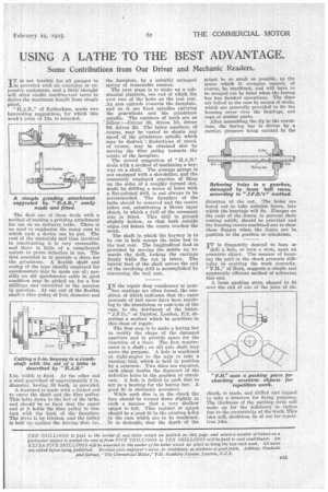
The first one of these deals with a method of making a grinding attachment for use on an ordinary lathe. There is Do need to emphasize the many uses to which such a device can be put. The cost of the materials and time involved in constructing it is very reasonable, and there is little of a complicated nature to prove defective in use. The first essential is to provide a drive for the grindstone. A flexible shaft and casing of the type usually employed for speedometers may be made use of ; possibly an old speedometer cable in good condition may be picked up for a few shillings and converted to the purpose in question. At one end of the flexible shaft a fibre pulley of 2-in, diameter and 1-in, width is fixed. At the other end a steel gearwheel of approximately 1 in. diameter, having 30 teeth, is provided.
A standard is made with a forked end to carry the shaft and the fibre pulley: This bolts down to the bed of the lathe, and should be so fixed that the upper end of it holds the fibre pulley in contact with the back of the faceplate. The drive iS by friction, and the pulley is held up against the driving slim, i.e.,
the faceplate, by a suitably arranged spring of reasonable tension.
The next stage is to make up a substantial platform, one end of which fits over two of the bolts on the tool rest. An arm extends towards the faceplate, and on it are fixed spindles carrying the gearwheels and the grindstone , spindle. The numbers of teeth are as follow :—Driver 30, driven 10, driver 60, driven 20. The latter numbers, of course, may be varied to obtain any speed of the grindstone• spindle which may be desired.'; Reductions of speed, of course, may be obtained also by moving the fibre pulley towards the centre of the faceplate.
The second suggestion of " deals with a method of machining a keyway on a shaft. The average garage is not equipped with a slot-driller, and the commonly employed practice of filing up the sides of a roughly formed slot, made by drilling a series of holes with a flat-pointed drill, is not always to be recommended. The faceplate of the lathe should be removed and the centre taken out, substituting a Morse taper shank, in which a drill of the necessary size is fitted. This drill is ground slightly hollow, so that both outside edges cut before the centre touches the work.
The shaft in which the keyway is to be cut is held across the lathe bed in the tool rest. The longitudinal feed is provided by moving the saddle up towards the drill, locking the carriage firmly while the cut is taken. The lateral feed of the shaft across the end of the revolving drill is accomplished by traversing the tool rest.
IN the repair shop crankcases or gear box castings are often found, the condition of which indicates that th outer journals of ball races have been revolving in the aluminium or cast-iron of the case, to the detriment of the latter. " J.F.D.," of Dalston', London, E.8, describes a method which he practises in this class of repair.
The first step is to make a boring bar to rectify the shape of the damaged aperture and to provide space for the insertion of a liner. The first requirement is a shaft ; an old axle shaft may serve the purpose. A hole is machined at right-angles to the axis to take a turning tool, which, is held in position by a setscrew. Two discs are required, each about double the diameter of the defective holes in the gearbox or crankcase. A hole is drilled in each disc to act as a bearing for the boring bar. A good fit is obviously necessary.
While each disc is in the chuck the face should be turned down slightly in such a manner that a very shallow spigot is left. This register or spigot should be a good fit in the existing holes in the ease which are to be machined. It is desirable that the depth of the spigot be as small as possible, as the space which it occupies cannot, of course, be machined, and will have to be scraped out by hand when the boring bar has finished operations. The discs are bolted to the ease by means of studs, which are generally provided to fix the housing cover over the bearings, end caps or similar parts.
s After assembling the rig in the crankCase, the boring bar is driven by a carrier, pressure being exerted in the .Reboring holes holes in a gearbox, damaged byloose ball races, according to "J.F.D.'s" method.
direction of the cut. The holes are bored out to take suitable liners, into which the bearings will fit. Flanges on the ends of the liners, to prevent their coming adrift, should be provided and the housing covers machined .out to clear these flanges when the liners are in position in the gearbox or crankcase.
IT is frequently desired to bore or drill a hole, or turn a stem, upon an eccentric object. The manner of beat'. lug the part in the chuck presents difficulty in centring the work correctly. "F.H.," of Bath, suggests a simple and apparently efficient method of achieving this end.
A loose packing strip, shaped to fit over the end of one of the jaws of the chuck, is made, and drilled and tapped to take a setscrew for fixing purposes. The thickness of the packing strip will make up for the deficiency in radius due to the eccentricity of the work. This idea will, doubtless, be of use for repetition jobs.