


Patents Completed.
Page 20
If you've noticed an error in this article please click here to report it so we can fix it.
Robey Suspension Improvements. Frictional Transmission Gearing.
A Compound Piston Ring. Rolls-Royce Camshaft Lubrication.
Copies of complete specifications of the patents published on this page can be obtained from the Sales Branch, Patent Office, Holborn, W.C., at the cost of sixpence for each specification.
Aitiineresting and improved form of frictional . transmission gearing.
C. M. P. MoNrnAnnoN AND G. E. entnnu, No. 235 of 1915, dated under the International Convention 26th January, 1914. —According to this invention the friction gearing is carried by a Y-shaped member set horizontally in the chassis. The fiction-disc lies transversely between the arms of the Y,. its drivin shaft being mounted in the hollow leg. The frictiondrum is mount etl to slide on a shaft which bridges the space 13( tween the two arms of the Y.
The drum is traversed across the face of the disc by a Clange-sped-lever, but provision is also made for obtaining greater pressure between the two members when transmitting at a low ratio. The friction-disc is pressed rearwardly by a spring abutment shown under the foot-boards. The abutment consists of a lever pivoted at one end on a thrust member for the disc, and the other end engages a curved arm. Ily varying the point of contact between the spring member and the curved arm, the leverage of the thrust on the disc is ;tried and this adjustment is obtained automatically by c:.epling the spring member to the change-speed-lever: LANCASTER AND .TONGE, LTD., and_ J. BUTTERWORTH, No. 11,767, dated 14th August, 19151—The accompanying drawings show a compound piston ring. It is built up of two expanding rings side by side, and a raised portion on each engages a circumferential recess on the other one, the edges of sea recess being bevelled to an angle of not more than 53 degrees with the flat surface of the ring. The expansion f the_rings acting through these wedging surfaces tends to farce them apart laterally and keep them tight edgewise in. the groove of the piston. The rings are provided respectively with a circumferential tongue and a groove to engage it, whereby they are retained co-axially. This tongue and groove tare shown in the fragmentary section in the drawings.
An alternative construction, in which the rings are expanded by a spiral tompression spring, is also described and illustrated in the specification.
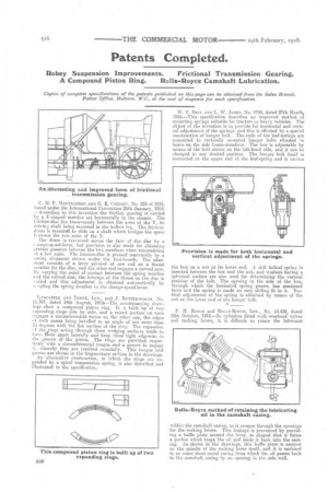
W. T. BELL AND L. W. JONES, No. 4799, dated 27th March, 1915.—This specification describes an improved method of mounting springs suitable for tractors or heavy vehicles. The object of the invention is to provide for horizontal and vertical adjustment of the springs, and this is effected by a special construction of hanger bolt.. The ends of the leaf-springs are connected to vertically mounted hanger bolts situated in boxes on the side frame-members: The box is adjustable by means of the bolt shown On the left-hand side, and it can ne' clamped in any desired position. The hanger bolt itself is connected at the upper end of the leaf-spring and. it caries.
the box on a nut at its lower end. A stiff helical spring is inserted between the box and the nut, and washers having a spherical surface are also used for determining the vertical position of the bolt. The opening in the side of the box, through which the laminated sprtng passes, has machined faces and the spring is made an easy sliding fit in it. Vertical adjustment of the spring is obtained by means of the nut on the lower end of the hanger bolt.
F. H. ROYCE and Rou.s-RovcE, Lin., No. 14,430, dated 12th October, 1915.—In cylinders fitted with overhead valves and rocking levers, it is difficult to retain the lubricant within the camshaft easing, as it escapes through the openings for the rocking levera. This leakage is prevented by proViding a baffle plate_ around the lever,. so shaped that it forms a pocket which traps the oil and leads it back into the casting. As shown in the drawings, this baffle plate is secured on the spindle of the rocking lever itself, and it is eneldsed in an outer sheet-metal casing from which the oil passes back to the camshaft casing by an opening in the side wall.