n Vehicle 77a,)=(22 FE -- )? by Preceptor
Page 15

If you've noticed an error in this article please click here to report it so we can fix it.
Steering, 3
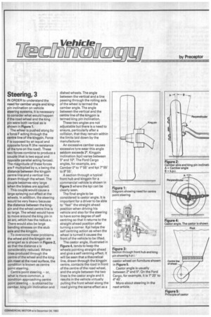
IN ORDER to understand the need for camber angle and kingpin inclination on vehicle steering systems, it is necessary to consider what would happen if the road wheel and the king pin were both vertical as is shown in Figure 1.
The wheel is pushed along by a force F acting through the centre line of the kingpin. Force F is opposed by an equal and opposite force R the resistance of the tyre on the road). These two forces combine to produce a couple (that is two equal and opposite parallel acting forces). The magnitude of these forces are F multiplied by x, x being the distance between the kingpin centre line and a vertical line drawn through the wheel. The couple becomes very large when the brakes are applied.
This couple would cause a large splaying out effect at the wheels. In addition, the steering would be very heavy because the distance between the kingpin and the wheel centre line is so large. The wheel would have to move around the king pin in an arc, which has the radius x. There would also be large bending stresses on the stub axle and the kingpin.
To overcome these problems the wheel and the kingpin are arranged as is shown in Figure 2, so that the distance x is considerably reduced. Where lines produced through the centre of the wheel and the king pin meet at the road surface, the condition is known as centre point steering.
Centre point steering — or, what is more common, a condition approaching centre point steering — is obtained by camber, king pin inclination and dished wheels. The angle between the vertical and a line • passing through the rolling axis of the wheel is termed the camber angle. The angle between the vertical and the centre line of the kingpin is termed king pin inclination.
These two angles are not adjustable but there is a need to ensure, particularly after a collision, that they remain within the limits laid down by the manufacturer.
An excessive camber causes excessive tyre wear this angle seldom exceeds 2°. Kingpin inclination (kpi) varies between 5° and 10°. The Ford Cargo angles, for example, are: Camber 0° to 1'55' and kpi 7° 55' to 13° 55'.
A section through a typical front hub and kingpin for a commercial vehicle is shown in Figure 3 where the kpi can be clearly seen.
The final angle to be considered is castor angle. It is important for a driver to be able to "feel" the straight ahead position when driving his vehicle and also for the steering to have some degree of self centring so that it returns to the straight ahead position after turning a corner. Kpi helps the self centring action as when the wheel is turned it causes the front of the vehicle to be lifted. The castor angle, illustrated in Figure 4, tends to keep the wheels pointing straight ahead and give a self centring effect. It will be seen that a theoretical line, drawn through the kingpin centre, contacts the road in front of the centre of the road wheel, and the angle between the two lines is the castor angle and it results in the vehicle virtually pulling the front wheel along the road giving the same effect as a castor wheel on furniture shown in Figure 5.
Castor angle is usually between rand 5°. On the Ford Cargo, for example, it is 1° 20' to 4° 40'.
More about steering in the next article.


