Vulcan Engines and the Bromide Blight
Page 24

If you've noticed an error in this article please click here to report it so we can fix it.
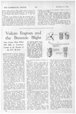
• Some Service Hints Which Will Help to Counteract -Certain of the Ravages of the M.T. 80 Fuel nPERATORS of Vulcan vehicles of 44--, the 6 V.F. 6-ton type, equipped with the 25.8 h.p. engine, will do well to study carefully the following features with a view to .reducing any troubles which they may now be experiencing in consequence of the use of leaded petrol.
The first point concerns tappet clearance; this should be .012 in; with the engine cold. If operating conditions be particularly arduous,.then the exhaust-valve i clearance . may be increased to .016 in. It is important to see that the tappets are resting on the base circle of the cam before any readjustments are made, and this can be assured if No. j. inlet valve be fully open when adjusting No. 4 inlet and No. 3. exhaust ; No, 2 inlet fully open when giving attention to No. 3 inlet and No. 1 exhaust; No, 3 inlet fully open when attending to No. 2 inlet and No. 4 exhaust; and No. 4 -inlet hilly open when adjusting No. 1 inlet and No. 2 exhaust.
The engine must be cranked, or allowed'to motor, for a few seconds if adjustments-are to be made following regrinding, otherwise the tappets may be set against 'a false position of the valve: In the case of the Vulcan engine, no modifications to the length of the exhaust-valve guide are called for, neither is a change in the material of the valVos under consideration. The standard exhaust valve is made from Sitchrome and exhaust valves and inlet valves are not interchangeable.
Stellite-faced exhaust-valve inserts have been fitted as standard from chassis 616 onwards, but inserts for earltr.tyres of 6 V.F, engine can be obtained on request. A loose insert can be detected by tapping. it with a light hammer. If it be looSe it will give a dull sound, without ring; any
such component should, of course, be replaced.
All valves have a face angleof 30 degrees, and the inserts must be ground true with a grinding stone, well supPorte0 to prevent chatter. The width of the seating should be in , and its concentricity with the valve guide ought to be within the limit of .002 in. As a general rule, small hair cracks extending outwards from the exhaust-valve seatings may be ignored, as it has not been found that perform. ance is in any ■.vay affected.
'There are three sizes of exhaust-valve insert, these being the standard, the _ .005-in. oversize, and the -Fte,-in.' over
size. When the standard insert is found to be on the loose side, the .005-in, oversize insert is to be Used. There is no need to carry out any retapping in this case, but when fitting the oversize insert it is necessary to retap the port, for which purpose the cylinder block should be returned to the maker.
Insetts must be fitted with a reasonable degree of tightness, with a certain amount of interference. This is decided by screwing the insert in for about two threads by hand, follciwed by a short-handled lever, and, finally, with a lever about. 2 ft. in length. .
If the operator does not possess the special splined tool for this purpose, one' can be Made by using a fin. B.S.F. high-tensile, steel bolt, with two nuts locked together.
If. the insert be but a few thousandths' of an inch proud of the port there is no need to bother, but any undue projection should be
removed by means of a surface grinder. When giving attention to exhaust Valves, those, the head thickness of which above -the seat is less than 1-32 in. after grinding, should be rejected. This also applies to the inlet valves: the reason for this is that, if the valve face lacks support there is a chance of the edge of the valve curling. The free or uncompressed length of the valve springs is 4 ins., and the loaded length 3 in. based on an imposed weight of 115 lb. It is advised that the ignition be advanced to a point just short of the " pinking " stage, a useful setting-being equal to 10 teeth on the starter ring before top dead centre, in the fully-advanced position, Lodge single-point type B.B.L. plugs should be used, the gap, being set to .022 in.—.024 in. -withcoil ignition or .016 in. with magneto.
With the Solex F.A.I.P. 40 car buretter, the main jet size is 140, ,Dealing with miscellaneous items, attention must be paid to the crank case-breather openings, exhaust pipes examined for sharp bends, dents or other obstruaions to the free flow of the exhaust gases, and care exercised in oil select-ion. From April to October' the recommended grade is S.A.E. 40, and from November to March, S.A.E, O.
Where an engine is not likely to be run for a considerable period, following the use of M.T. 80, it is a wise precaution to spray engine oil into each cylinder via the sparking-plug hole,. the engine being turned slowly in order to distribute the oil over the cylinder walls.


