


A Power operated Windscreen washer
Page 70
If you've noticed an error in this article please click here to report it so we can fix it.
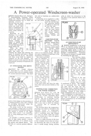
FROM Daimler-Benz A.G., StuttgartUntertiirkheim, Germany, comes patent No. 750,735, which discloses a windscreen-washing unit in which the spraying po wer is derived from the intake suction. The spraying action can occur when there is temporarily an absence of suction, the power being stored by a spring.
Referring to the drawing, 1 is a piston worked by the intake suction and controlled by a slide valve (2). During running, the piston is sucked upwards against a spring (3) and held there by a spring detent (4).
When the driver requires the spray he pulls the knob (5), releasing the detent and allowing the piston to descend and force a charge of liquid from the jet (7). The device will then re-set itself by suction in readiness for the next demand. The liquid is stored in the reservoir (8) and conventional pumping arrangements are employed.
AN EXHAUSTER FOR SERVO BRAKES
PATENT No. 752,061 (Clayton Dewandre Co., Ltd„ Titanic Works, Lincoln), deals with an exhauster pump for suction-operated brakes. The chief
points of the design are the provision of a constant-pressure valve and a method of providing lubrication using the suction effect of the pump.
The pump works on the eccentricvane principle, a vaned rotor (1) revolving in an eccentric cylindrical casing (2). The suction is created in the upper region where spaces 3 are expanding, the air being discharged from a lower port (4).
To provide a constant pressure in spite of high engine speeds, a springloaded ball-valve (5) is placed across the suction and exhaust spaces. The ball lifts at a pre-set pressure differen
c32 tial, and so functions as a safety-valve in reverse.
Lubricating oil is supplied to a filtei (6) and passes through passages 7 to reach the end bearings The generated suction is sufficient to draw the oil into the unit. Three other patents from the same source refer to the exhauster and .related matters; their numbers are 752,062, 752,063 and 752,064.
INJECTION-PUMP DELIVERY VALVE
FROM Daimler-Benz A.G., StuttgartUntertfirkheim, Germany, comes patent No. 751,160, which deals with an improvement in the delivery valves of, an injection pump. The aim is to give a measure of suck-back at the termination of injection.
The valve is provided with two diameters, as shown at 1 and 2. The smaller diameter seals the exit from the pump chamber when in its bottom position. On the injection stroke, the valve is lifted until the larger diameter clears cross-ports (3), which then pass the fuel. On the succeeding downstroke, the cross-ports are first closed, but the valve has farther to descend before its bottom face seals. It is this final action that gives the suckback effect and prevents dribble at the nozzle.
• TEMPERATURE CORRECTION FOR POWER STEERING
FROM Ford Motor Co., Ltd., 88 Regent Street, London, W.1, comes patent No. 751,903, describing detail modifications to powered steering systems. The aim is twofold; to provide a restricted hydraulic path to prevent the power coming into action with a jerk, and to allow for changes in viscosity due to extremes of temperature.
The drawing shows the temperature correcting unit which is included in the hydraulic circuit. A temperatureresponsive capsule (1) is arranged to work a restricting valve; this consists of a nose (2) which, under hot conditions, is forced into a bore (3) against the action of a spring,
There is a slight clearance in the bore so that complete closure does not °tali. As illustrated, the valve is in the position it would occupy during extreme
cold, in which the obstruction to the free flow of the hydraulic fluid is at a minimum.
AN INJECTION-PUMP REFINEMENT
A SIMPLE modification to the barrel 1-1 of an injection pump, having the object of increasing the fuel charge with increasing engine speed, is shown in patent No. 752,261 (Daimler Benz A.G.,
Stuttgart Unterthrkheim, Germany). The increase in charge is brought about by throttling the spill ports.
The drawing shows, in full line, a standard helically edged plunger, and in broken line the position of the spill ports in the barrel. The large bore (1) represents the usual port; this is not present in the barrel and is shown only for comparison. The upper port (2) is the normal inlet.
Instead of the one large bore, it is proposed to use three smaller ones (3, 4 and 5) positioned as shown. The smallest one is uncovered first, the middle one next and the large one last. This brings .about a gradual release of surplus fuel, and thus gives the required throttling. Instead of three holes, a single triangulated port can be used.
The arrangement as described is for pumps in which the main variation in fuel feed is effected by adjusting delivery termination by the helical edge of the plunger.