


AN . EPICYCLIC CHANGE-SPEED GEAR.
Page 28
If you've noticed an error in this article please click here to report it so we can fix it.
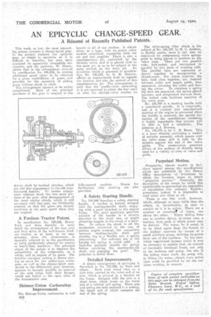
A Résumé of Recently Published Patents.
This week, as last, the most .interestlag patent concerns a change-speed gear. In the present instance the epicyclie gear, as Simple in -operation as it is difficult to describe, has once More exercised its apparently irresistible fascination, and the patentee, W. Mason, claims that in the arrangement_ covered by specification No. 146,668, he enables additional speed relics to be obtained far a given corehirration of gears, and provides for the operation of sliding gears without shack or clash. The arrangement appears to be rather complioated. Each of the principal members of the gear is coupled to the
driven zhaft, by toothed clutches, which are slid into engagementin the old timehonoured fashion. To ensure engagement without shock the two main portions of the gear, after disengagement of • the usual engine clutch, which ii still necessary with this gear, are frictionally coupled, so that the gears are already revolving at the same speed when they are coupled.
A Fordson Tractor Patent.
In specification No. 129,626, Henry Ford and Sons desoribe in some detail the arrangement of the rear axle and final drive of the well-known Fordson tractor, or at least, an we may presume, since the construction is specially referred to in the specification as being particularly adapted for tractor or heavy-duty machines. The principal object of the patent is to improve the accessibility of the component, as a whole, arid in respect of its parts. The
• familiar one-piece casting is shown serving as cover for the under-type wormgear, as well as the change-speed gear. ACCES.b to the differential gear, however, appears to besonly possible on removal of the axle tubes with their flanges, which are bolted to the open sides of the transmission case.
Skinner-Union Carburetter Improvement.
The Skinner-Union carburetter is well • B34 known to all of our readers. It stands alone, as a type, with its piston valve suction controlled, regulating boththe air and fuel supplies. There it, also a supplementary jet controlled by the throttle valve, and it is placed cleSe to the Main jet, so as to be subject to the same suction, as the main jet. An invention which is patented in speeifioce tion No. 146,643, by G. H. kinner, effects an improvement both as regards the location and also the control of this supplementary jet. The arrangement is such that the needle-valve controlling it is not operated to admit the fuel until or after the throqle-valve reaches its
A Safety Starting Handle.
No. 146,686-describes a safety starting handle. A ratchet is formed integral with the slarting-handle shaft, engaging with a pawl attached to the engine frame. The .pawl positively prevents rotation of the handle in a reverse . direction to the usual one,as might otherwise happen in the event of a back
fire. To relieve the shock to all the mechanism concerned in the ease of ; sudden engine reversal, the connection between starting-handle shaft and starting dog is a flexible one, a spring intervening. For ordinary use of the handle. the spring is coiled solid. A back-fire partially uncoils the spring ;before revolving the starting-handle shaft, and engaging the pawl. The patentee is Baron Rose.
Detailed Improvements.
A simple arrangement of springing is des.exibed in No. 137,039, by Beck and others. Each road wheel runs on a. stub axle, carried at the outer end of an arm, which is pivoted in a bracket on the frame. Integral with the arm is a short lever, which bears on the lower end of a vertical coil spring. Short arm and spring are both enclosed in a casting, the upper end of which restrains the end of the spring.
The valve-spring lifter which is the subject of No. 146,737, by H. C. Jenkins, is doubly useful, since it caw also be employed for compressing valve springs prior to being placed in position on the valve stem. There are two parallel rods, fork-ended, and maintained in parallel by two pairs of coupling rods: The parallel bars• are separated or ,drawn together by mardpulating a thurrib-screw. For cotter removal, the bars, held close together, are inserted between collar and tappet guide, thee separated, elevating the collar and freeing the ,cotter. To compress a spring the bars are separated, the spring placed between, and compressed between them. The forked ends facilitate insertion of the valve stem.
No. 146,766 is a starting handle with a castellated spindle, it ia. remoYable, and it is claimed that unauthorized starting of the engine is prevented when the handle' is removed; the special formation ofthe castellations rendering it highly ixn!probable that anyone will be able to find a substitule. The patentee is 3. Downes.
No. 146,770 is hy C. H. Rowe. This is a. loose thimble containing a washer of suitable material, which passes over
• the valve stem, and is held by the thimble against the end 01 the valve guide. The construction patented allows of one pattern of thimble being guuseidde.for a variety of sizes of valve and
Perpetual Motion.
Frequently, almost weekly in fact, there appear among the specifications which are pnblished by the Patent Office descriptione of inventiosis by which the inventor hopes to attain
'' perpetual motion." Generally,' the description of the means by which this unattainable is approached are impossible of translation into ordinary English; sometimes, indeed, it is impossible to read sense into them at all.
There is one this week, however, Whidh, although no more futile than the others, is, nevertheless, as easy to explain as it is to refute.. There are a number of reservoir* of water, one above theeother. "Water 'falling from one to another. drives, in every cage, a turbine, from cleft of Which power may be derived. The water, be it noted, is to be lifted again from the *lowest to the highest reservoir by means of a small auxiliary pump, deriving its power front one cf the turbines. To the eke-. lately -uNnitiated layman (only) it may be necessary to explain that, on account -of inevitable frictional lezses, not only in the turbines and pump, but also in the falling water itself, the pump will, in lifting the water, aheorb snore power than could be provided by all the turbinesworking in concert.