


THE STRAKER-SQUIRE 3-5 TON CHASSIS.
Page 20
Page 21
Page 22
If you've noticed an error in this article please click here to report it so we can fix it.
A Detailed Description of a -Chassis Embodying Many Original Features.
41BRIEF DESCRIPTION, Which
included the salient features of
e Straker-Squire, A-type chassis, mid, incidentally, the first details published of this interestiug product, was contained in our issue dated December 9th, 19L9. At the conclusion of this article we made a promise to our readers that we mould, at a later date, publish a detailed de.teriptien of the chassis, and though production is now increasingrapidly, with ' the result that a fair _number of these chassis have already -heed delivered,' and thus a•certain number Of people are . probably cognizant with the design, .yet it incorporates so many interesting and novel features that we have no hesitation in dealing with it at Seine length.
The A-type chassis is intended for use' either as alorry:, eharea-bancs or bus, and it is peculiarly fitted to fulfil the con, eitione ,required for each phase of. work. As a lorry; owing to the position of the en ;Me, it can efirry a load of 5 tons without the load on the back tyres exceeding the 6-ton limit allowed by law. As a cliar-A, banes, and foi: the wilereason, . it can-carry 35-46 persons, inoluding the (Liver, and this without excessive overhang, as would be the case with a . vehicle following standard design. Fry • n given win el...ase the Stralser-Squire givesapproxirnitely 2 ft. more body Space than the majority of chassis designed for public service work, the actual lear length Of frame for the body _ being 19 ft. 7 ins., and that with a
wheelbase of 14 ft. 6 ins. only. .
Steering is one of the most imPortant points in char-C-banns construction, as these vehicles must Marnettvre with the greatest ease' particularly .in view of the outcry whiclii is at present being made against them, and in the chassis under discussion the • diameter of the
tut sting circle is 53 ft. ,
Forlorry work the final gear ratio is 8 to 1, and for passenger work (except in very hilly districts) 7 to 1. In addition, certain allowances are made in the strength of the, springs to suit the drtferent working conditions. On test, with a 5 ton load, over •a, give-and-take fond, and with the 8 to 1 ratio, the ., vehicle averages just over 7 m.p.g.; and running light, slightly over 8 m.p.g. With the 7 to 1 gear ratio, and a similar
load, it averages 8 m.p.g., or without load 9 m.p.g., and with a st<4.ndard engine 75 ton-miles per gallon can be achieved. The great advantage of the overheadvalve engine is splendid pulling power at low speeds, as well as extra power at high speeds. As regards weight, the manufacturers claim that they, have .obtained strength Combing(' with comparatively low weight, the weight of the bare chassis being 3 ton 7 cwt., and _this with all heels of the same diameter fitted with 1,030 mai. by 140 mm. section tyres.
The springing is the best we have Observed On a commercial vehicle. The front springs at 4 ft. 3 ins. by 2i ins., and the rear springs 5 ft. 6 ins, by 4 ins. The latter are under-slung. Particular care has been taken in the design to make the springing equally effective with light or ' heavy loads by providing large cob springs at the rear' which, when the
chicle carries: its full load, take 25 _per eent, of this, and goout of action when the vehicle is running light. These springs are of ;round-section material, tapered to give progressive action, In order to prevent the. auxiliary springs from twisting the main frame side members, the brackets are bolted to the frame braces as well as to these members.
Much consideration has been givento that important. pe son, the driver. 'The steering is particularly light, and the column well raked. . This combined with a 20 ins, steering wheel and the excellent springing •ofthe front of the chassis, renders the drivers woik en-viable as compared With tha£ on certain vehicles of which we have cognizance.
A point, in the operation of the brakes, 'both hand and foot, is that the leverage increases as the broke , is ,. applied, so that their application is rapid, and when applied the foot pressure required for their operation is reduced: The clutch, being a single steel dis:: g-ripped between two rings of Ferodo, is very light, and thus facilitates gear changing. Four speeds and a reverse are pro
vided by the gearbox. The changespeed mechanism is all carried by the latter, and is thus unaffected by frame torsion.
The cooling arrangements have proved eminently Eatisfactory.
However excellent the design of a chassis may be, this design must be backed up by the employment of suit
able materials and in this connection the A-type chassis excels. The quality of the materials employed in it may be summed up as the best possible. Such important points as steering arms are constructed of speeial nickel steel, which will stand the smithy fire. The crankshaft is of 60 ton nickel chrome steel, whilst all the gear and driving shafts are of oil-treated chrome-vanadium, a material which has proved excellent in torsion. For the gears themselves 110 ton air-hardened nickel-chrome steel is employed.
Having given a general description of the chassis, which will appeal to those who do notwish to enter to any great .extent into technicalities, we will proceed with a detailed description. For the frame, pressed channel-steel side members are employed, but these are turned out instead of in, and as the cross membersare invariably held in position by bolts, replacements can easily be effected in the event of accident without dismantling the whole frame. At the i front end s a heavy, cast-steel crossmember, which supports the front end of the sub-frame, and also the starting handle. Amidships is a stout tubular member arched to allow room for the rise and fall of the cardan shaft, whilst at the rear is another cast-steel member, extensions of which act as spring brackets. From this cress-member a one-piece brace extends to each sidemember, and in the spaces between this brace and the side-members are bolted the supporting pieces for the auxiliary spring brackets.
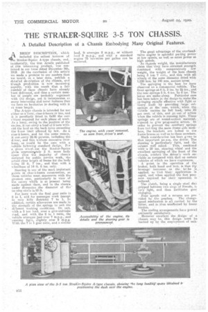
Perhaps the most interesting features of the chassis are embodied in the engine. This is of the-overhead type, in which the valves are operated through the medium of long push-rods and rocker-arms. The • rocker-arm arrangement forms the subject of one of the drawings which We reproduce. The rocker itself is held by a stout, flat spring, the slight movement of which causes no wear or noise. The push-rods have hardened steel socket-ends bearing on hardened pins, which are adjustable in the rocker arms. The four cylinders are cast en bloc with the top half of the crankcase, the cylinder heads forming a single casting, held by long studs pass ing right through it., by studs have a diameter of in. at the bottom, which dimension continues for 4 in. alter the thread, and is then reduced to# in., with the result that, if by any chance a stud be broken, the point of breakage will not be in the lower threaded pertiou
of the stud.
Two bearings only are employed for the crankshaft, but as this is 3 ins. in diameter, and comparatively short, no signs of whipping have been observed. It runs in two 7 ins, diameter roller bear.
ings held in the crankcatie by steel caps, and is locked endways by a double ballthrust bearing. The gudgeon pins, which are l ins, in diameter, . are clamped to the connecting-rod small ends, and bear in phoSphor-bronze bushes pressed into the pistons.
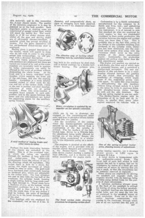
For the circulation of the cooling water the .thermo-syphonie principle, assisted by an impeller driven from a euntinuatioe• of the fan spindle, is utilized. The fan itself. is of the four. bladed type, driven by a Whittle belt, the adjustment being easily effected by moving one of the pulley flanges, the pulley being constructed in a• similar way to the adjustable pulley on a motorcycle.
The magneto is situated at the offside of .the engine, and is provided with an impulse sCarter designed and constructed at the Straker-Squire works. This little device renders starting a matter of little difficnay, and it is thrown out of adieu immediately the engine starts. Carburation is by a Smith carburetter, manufactured for the company by S. Smith and Sons, Ltd., and embodying special features. In connection with this instrument, it is of interest to. note that standard jet sizes are employed for every engine, as they are remarkably consistent in their power production, the variation between one engine and another being not More than 1 hp.This is probably due to the fact that, owing bo the design of the cylinders ensuring even thickness of the cylinder walls, distortion has been eliminated, also the overhead valve system does away with the variations which occur in the valve pockets of the more conventional engine. Incidentally, the production engines are pulling even better than the first experimental model.
The engine and gearbox are carried on a sub-frame, the front end of which rests on gunmetal brasses, and is permitted a quarter-inch movement. The rear suspension of this sub-frame is by a crossmember situated between the gearbox and the clutch, thus preventing the possibility of whipping, whioh might occur if the supporting points were wide apart. To assist this eress-niember in strengthening the side members without being stressed unduly it is held to the latter by bolts in clearance Ircles, with phosplhor-bronze plates between its ends and: the side members. The bolts are spring loaded to one ton each. The Straker-Squire engine, with its dimensions of 14 in. bore and 6i in. stroke, is smaller than many other engines employed for vehicles with a
similar loading capacity, yet it develops greater power; at 1,000 r.p.m. it averages 54 blh.p.
A novel device is incorporated with the carb-uretter-control joints. The lower half of each ball socket is held against the ball by a spring, but can be withdrawn by moans of a small pin and locked out of action by turning this pin into a catch, so that the connections can he instantly removed or replaced.
Silent chains are employed for driving the camehaft and magneto shaft, the magneto bracket with it bearings being movable along slotted holes for the purpose of chain adjustment. A valveless oscillating plunger pump at the back of the camshaft is utilized for forcing oil along the hollow camshaft. The camshaft bearings are Imbricated by radial holes, and the cams dip into the oil contained in the camshaft tunnel at each revolution. Ports cut in the two centre bearings communioate with nozzles in the. crankcase, through which jets of oil are squirted into the path of
centrifugal oil scoops, stamped solid with the crank: webs, and leading by drilled -holes to the crankpins. This system prevents a slack bearing from absorbing most of the oil, as sometimes occurs in „the ordinary forced lubrication system. The engine is situated in the conventional position, but the dashboard and driver's seat are brought forward, sothat the rear part of the engine protrudes through the • dash, where it es covered by a small bonnet.
-The radiator is also of the. conventional built-up cast aluminium type with gilled tubes, and is carried on rubber buffers on the front cross-member.
The drive is taken through asingledied clutch, provided, with a eery . efficient clutch stop, to the primaryshaft of the four-speed-and-reverse gearbox. Owing -to the way in which the engine and gearbox are lined. up on the subframe, no universal joints have to be introduced between them, splines on the primary shaft keying directly into others on the clutch centre.
The gearbox itself is.a one-Piece casting, giving-very rigid construction. The laysheit, which is carried on roller bear; ings, can be withdrawn complete with its pears and bearings for replacement or repair without any difficulty. The gate
box is carried any thegearbox, the selector gear being totally enclosed and working in oil.
The front cardan joint of the' cardan shaft' is socketed into the end of the gearbox shaft, and held in position by two bolts. The withdrawal of
the latter permits the 'front portion of the cardan theft to be dropped, and the. gearbox can then be removed' from the gule-frame without dis-. turbing the clutch mechanism. Both the front, and rear cardan joints are of the star type, and provided with blind bushes. Spring .and felt washers betweenthe centre of the star and each bush render the whole joint
dirt and oil-proof. The star piece has in. holes drilled.
through it in both diiections, and a separate plug enables it to be filled with oil. The universal joints have been tackled in a thoroughly practical manner, and a constant source of trouble has been eliminated. The cardan shaft is a large diameter steel tube, to which the joint forks are welded. The final drive is by overhead worm gearing, supported, together with the differeutial, by the cover of the pot-type rear axle. The stout axle ceding is a ene-piece casting. which includes the sprite seats, and which is carried right tip to the wheels.
The hollow-spoked cast-steel read wheels run on steel sleeves, 4 , ins, in diameter, pressed into the axle easing. Thephosphor-breeze wheel bushes are fixed an position, and each has a inege grease pocket at the top. A point about) the wheels is that in the ease -of those at the front the centre portion of the rim is dispensed • with, thus reducing their weight to a certain extent, and assisting the foundry operations.
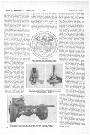
We have already mentioned the wonderful springing. of. this chasers, and it is, we believe, the best-sprung machine which we have yet had the pleasure of inspecting. The ordinary type of spring shackles -has been dispensed with, and a special type, in Winch hardened steel balls work in chilled-iron -Cups, is employed for the front suds of thu rear springs and the rear ends .of the front springs. The other ends of tleese ePriuge ereprovided With cast-iron slippers working on feed balls, -and enclosed in eases, which permit half-inch lateral movement in each direction. The reason for this allowance for lateral -movement mey not at first be understood ; • we will, therefore:explain—it in detail. When a cambered spring is depremed, it naturally elongates, and if one wheel lifts more than the other, the spring at that side of the chassis will elongate more then that on the other, with the result that the axle Will twist, and, where ordinery shacklesare employed, these havei.e bear the twist,mg. strains. Since the reareende of the ' backsprings are allowed half-inch lateral play, no twisting strains can be traneMitted to the main frame.
Hand and footbrakes operate brakeshoes situated side-by side in the rear wheel drums. These drums are 22 ins, in diameter, giving a very large braking area. The brake-rods -are made of flat strip steel, which can be twisted slightly witn the axle withoet, lock-nuts becoming unscrewed, as so of ten happens when screwed rods are employed. The brake and ' certain other levers are keyed on to their tubes in a simple but efficient manner by means of a key washer held by a bolt, as shown in-one of the sketches which we reproduce.
Attention might here be drawn to the-fact ,that thewhole Of the brake link-work, e with the exception of the cam 'spindles in the back axle, is fitted with oilless graphite bronze bushes; which require no lubrication whatever. Twenty of these bushes are employed, representing 20 points, Which, in. an ordinary .car, would require attene Con, but procaably would not get it.' Limitation of apace prevents. us -from going more fully into certain details, which merit lengthy' treatment; for instance, the Awivel aide pine are in one with the swivel axle forgings. The dust covers on-the latter are separate, so that a large radius can be given to each. axle, as the small radiused corners for the bearings can be formed by the covers. Another point of _great interest is that the engine and gearbox, including the clutch withdrawal mechanism, are carried on an enormously strong three-point suspended sub-frame, and can be removed as a unit when required:
The output of these chassisis now well upe to expectations, and reasonable . delivery can be given,, while to-day's price is L1,300, including tyres. It is clear that in its design the A-type Straker-Squire chassis displays much original thought.