


Fixed versus Live Axles.
Page 12
Page 13
If you've noticed an error in this article please click here to report it so we can fix it.
(Continued from page 443.1 Whereas a live axle is necessarily round, to secure the least weight for the required strength, a fixed axle may be of any cross section suitable to the design of the vehicle. In the Wolseley omnibuses the axles are circular in section ; in the Straker-Squire square; in the Orion square with the edges chamfered off. In the Milnes-Daimler vehicles axles square in section but bent are used. With a fixed axle the bearing springs are bolted to the axle, which generally has a flat place forged on it for this purpose, whilst lugs are often provided as well for the bolts that secure the springs. The axle is, therefore, free to rise and fall with the inequalities of the road surface, but does not revolve with the wheels. If a chain drive is employed, or a pinion drive on an internal gear ring, the axle is kept in its right place relative to the differential countershaft by radius rods, or, as in the case of the Dennis worm drive, by horn plates between which It rises and falls. In the Wolseley and Straker-Squire -axle the wheels are arranged at right angles to the axle, but in the Orion and Milnes-Daimler omnibuses the wheels are dished. This splaying is to allow for running on the rounded surface of the road and also to ensure that the weight transmitted through the axle to the wheel tends to press the wheel against the shoulder of the journal and not against the collar on the axle-cap side. The weight is thereby employed to aid in keeping the wheels on and to avoid any tendency for their leaving the axle.
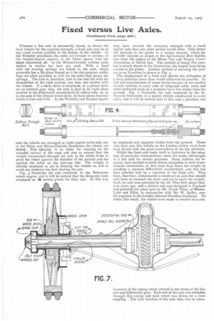
Fig. 4 illustrates the axle employed in the Robertson steam wagon, and it will be noticed that the designers have employed an H section girder for their axle. In this way
they have secured the necessary strength with a much lighter axle than any other section would allow. They fasten the journals to the girder in a unique manner, which deservedly secured an award at the Agricultural Hall Exhibition from the judges of the Motor Van and Wagon Users' Association in March last. The method of fixing this journal is clearly shown in the illustration, the forged arms being riveted to the girder. Another method of securing the journal to an H-section is shown in Fig. 5.
The employment of a fixed axle admits the utilisation of a lorry platform lower than would otherwise be possible. In fact one manufacturer of motor lorries has put on the market several vehicles to carry rolls of telegraph cable, safes and other awkward loads on a platform but a few inches from the ground. Fig. 6 illustrates the axle employed by the St. Pancras Ironworks in a special vehicle constructed to carry safes, and it will be noticed that in this case a platform can be employed only eighteen inches from the ground. Those who have met this vehicle on the London streets must have been struck with the great convenience of the low platform.
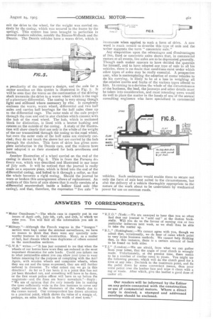
Whilst the fixed axle lends itself to lightness by the adoption of particular cross-sections, there are many advantages in a live axle for certain purposes. Some makers, for instance, have decided to avoid chains altogether in their transmission mechanism, or they have kept down the weight by avoiding a separate differential countershaft, and this has been possible only by a rejection of the fixed axle. They have, therefore, endeavoured to construct an axle that should on12:7, have to transmit the drive and not to carry the weight. Such an axle was patented by the De Dion firm about fourteen years ago, and a similar axle was designed in England and patented two years later by Mr. Frank Elliot, of Messrs. Lake and Elliot, in conjunction with Mr. W. Spiller, now the engineer to the London General Omnibus Company. To attain this result, the wheels were made to revolve on a con tinuation of the casing which covered in the whole of the live axle and differential gear. Each end of the axle was extended through this casing and each wheel was driven by a claw coupling. The only function of the axle then was to trans mit the drive to the wheel, for the weight was carried entirely by the casing, which was secured to the frame by the springs. This system has been brought to perfection in several modern vehicles, notably the Simins-Welbeck and the Dennis. The Dennis vehicles have a worm drive, which is a peculiarity of the company's design, and the axle for a motor omnibus on this system is illustrated in Fig. 7. It will be seen that the worm on the continuation of the driving shaft transmits the drive to a worm wheel which is the cage of a planetary differential. The casing is very strong though light and stiffened where necessary by ribs. It completely encloses the worm, worm wheel, differential and two half axles and carries ball bearings for the half axles close up to the differential cage. The outer ends of the axle project through the case and end in star clutches which connect with the hub of the road wheel. The hub, which is sectioned black for distinction, is lined with a bronze bushing and rotates on the outside of the casing. A study of the illustration will show clearly that not only is the whole of the weight of the car transmitted through the casing to the road wheel, but even the outer ends of the half axles are similarly carried; they do not touch the sleeve but are carried by the hub through the clutches. This form of drive has given complete satisfaction in the Dennis cars, and the makers have now adopted it as their standard for both omnibuses and lorries.
Another illustration of a wheel carried on the end of the casing is shown in Fig. 8. This is from the Parsons delivery van, which was described and illustrated in our issue of July 20th. It will be noticed that the journal is really made as a separate piece, which is fitted into the end of the differential casing, and bolted to it through a collar, so that the whole becomes a rigid casing. Should the journal be worn or broken this arrangement allows of replacement. An analysis of this form of axle shows that it really consists of a differential countershaft inside a hollow fixed axle (the casing), and that, therefore, the expression "live axle" is
inaccurate when applied to such a form of drive. A new word is much neeued to describe this type of axle and the writer suggests the term " concentric axle."
Any disquisition upon the advantages and disadvantages of live, fixed or concentric axles shows that, in commercial motors at all events, live axles are to be deprecated generally. 'Though each maker appears to have decided the question for himself, and to have adopted one type of axle in all his vehicles, there is no doubt that conditions exist under which other types of axles may be really essential. A prospective user, who is contemplating the adoption of motor vehicles to do his carrying, is likely to be at a loss in weighing all the relative merits and faults of the various types offered to him. In coming to a decision the whole of the circumstances of the business, the load, the journeys and other details must be taken into consideration, and most intending users would do well to place the matter in the hands of one of the several consulting engineers who have specialised in commercial vehicles. Such assistance would enable them to secure not only the form of axle best suited to the circumstances, but also the delivery of a vehicle thoroughly appropriate to the nature of the work about to be undertaken by mechanical power for use on common roads.