


TO CONTROL THE AXLES OF SIX-WHEELERS.
Page 74
If you've noticed an error in this article please click here to report it so we can fix it.
A Résumé of Recently Published Patent Specifications.
PECIFICATION No. 287,315, by 0.1,eyland Motors, Ltd., and George John Itackhans, describes a method of rontrolling the axles of six-wheelers so r as reaction torque due to the . drive of the worm is concerned,_but at the
same time allowing movement to take place in other directions. The upper view shows two driving axles of the under-worm type, in which a fiat, springy member is rigidly secured to the lefthand worm box, and is provided with a cylindrical extension which May slide in a long boss attached to the worm box on the right. By this means sliding and rotary imovernents are permitted, but rotary movement of the axle sleeves is prevented by the broad, flat member. This member, being of fat section, as shown in the plan view, can act as a spring and so allow independent movement of the axle sleeves in any direction excepting that produced by reaction torque, • A New Single-operation Lubricating System. TITE name of Tecalemit, Ltd., is so well known in connection with recent improvements in lul-ricating systems that any forther development emanating from that 'concern should be of interest to designers and users of commercial motors. • Any devica which will tend to ensure libricant getting to the exact spot where it is • required should have a great .effect in reducing the cost of upkeep, as lack of lubrication is nearly always at the root of all troubles which ;entail costly renewals.
In the apparatus • described in patent specification No. 272,963 there is a reservoir for oil which can gravitate into a pump worked by a large piston actuated by vacuum or pressure from the engine. A stroke of. this pump delivers oil at a considerable pressure to the two distributing cylinders shown, a single movement of the driver being sufficient to cause a forward and return movement of the pressure pump.
The lower view is a sectional view of one of the distributing cylinders, the pipe at the left-hand end being that which leads oil from the pressure pump, the piston in the distribry:ng cylinder automatically distributing the oil between the seven duets shown.
The distribution is accomplished in thefollowing manner. The pressure acts upon the piston (A), closing the valve (B) and forcing the tube connected with (A) towards the right, 113 272,6453
thereby compressing any oil that is in the tube (C) until some means of escape is found. Holes are drilled !through the tube (C) at (D), and a groove is turned on the outside of the tube to help the oil to escape when the hole (D) comes opposite any of the ducts.
It is claimed for the invention that when opposite a duet the pressure will enable that .duct to receive what amount of oil is necessary to fill it,; and to fill any cavity to which it may lead. When this is done, and the duct can receive no more oil; the pressure. from the pump will reassert itself and
cause the tube (C) to move a ste farther, when it will come opposite ; another duct, which will receive what lubrication there is room for, and when full the SAM thing will occur again until all ducts have received their fill of oil.
Provided that the bearings to which the ducts lead are in good condition and will offer a reasonable icsistance to the entrance of any more oil than they should take, all will be well, but our experience of central lubricating systems in the past has been that through lack of supervision one bearjog is permitted to develop sufficient clearance to allow the escape of lubricant, thus reducing the pressure and starving all other bearings.
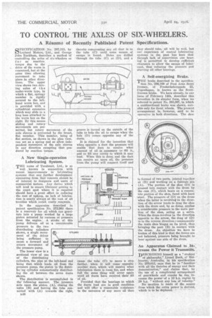
A Self-energizing Brake.
THE brake described in the specifica tion No. 286,169 of Pont Arne Scott' Iversen, of Frederiksborggade 25, Copenhageo, is known as the ScottIversen brake. We have already, in our issue of Febrnary 14th, described this invention in its simpler form, when we referred to patent No. 283,387, in which a unidirectional brake was shown, suitable only for front wheels. The present arrangement is, however, said to be operative in both directions. The shoe is formed of two parts,jointed together at (B) and working on a fulcrum pin (A). The portion of the shoe (D) is .pressed into contact with the drum by the cam (C), which bears on a concentric portion of the shoe, faced with hard steel. The pressure of (D) on the drum. when the latter is revolving in the direction of the arrow tends to drag the shoe with the drum and, by so doing, applies a considerable pressure to the main portion of the shoe, acting as a servo. When the drum revolves in the direction opposite to the arrow, the drag of (D) is in the reverse direction ; consequently the main shoe hinges on its pivot, thus bringing the part (E) in contact with the drum. An objection we have to brakes of this kind is that the forces are not balanced, pressure being brought. to hear against 'one side of the drum.
An Apparatus Claimed to .111-1, crease the Power it TransmitS:'. .
DESCRIBING himself as a " studebt
philosophy,"; Lionel Puck, of Mel' bourne,' Australia, in his specification No. 279,013, says that he is "familiar •• with all the theories of energy' and their demonstration," and claims that, by the use of a complicated arrangement of gearwheels and cranks he can • increase the power of a 10 h.p.. engine to 20 h.p. "without any loss of velocity." No 'mention is made Of the source from which the extra power is derived. which iy.s to be dep/ored.' • •