


An All-way Tipping Body
Page 52
If you've noticed an error in this article please click here to report it so we can fix it.
A Resume' of Recently Published Patent Specifications
THE usefulness of a tipping body is greatly enhanced if the load can be discharged in any direction, and a scheme whereby this is achieved forms the subject of patent No 505,513, by Alexanders of Edinburgh, Ltd., Temple Street, Edinburgh.
This concern uses a simple end-tipping body, the whole mechanism being mounted on a turntable so that it can be rotated to discharge at the sides, rear or cornerwise; the drawing shows the last-named position. The tipping mechanism is worked hydraulically, a fluid-tight glarfd being provided at the turntable centre. On machines for light loads the turntable can he rotated by hand, power-operation being arranged for on the heavier models.
A Constant-velocity Universal Joint. A UNIVERSAL joint of novel construction forms the subject of patent No. 505,535, from Bendix Aviation Corporation, Chicago, U.S.A. From each shaft projects a pair of arms provided with semi-circular race-ways (I). The two sets of arms interlock and form cylindrical housings for four balls (2), these forming the torque
transmitting members. The joint is prevented from separating by a partball (2), which engages with each of the shaft member4.
When the joint is deflected, the bails roll in their housings until they bisect -the angle formed by the shafts.
Improved Drive for Engine . Auxiliaries.
ASCHEME for driving the injection pump; dynamo, magneto, or other auxiliaries is described in patent No. 504,393, by A. Stubings, Olde Timbers, Holtwood, Aylesford, Kent. This inventor states that the usual timinggear arrangements, in which some of the gears are carried by the spindles of the auxiliaries they drive is usually noisy, and, moreover, is not good from the production standpoint.
The improved scheme is to mount each gear of the timing train on its own bearings, so that its position, with respect to the crankshaft, is definitely located, whilst each of the subsidiary shafts is driven by a splined coupling. Referring to the drawing, the crankshaft (3) drives its pinion via a V-spline, the pinion's own bearings being clearly shown. Similarly, the camshaft (2), the oil-pun:1p spindle (4) 42 and the injection pump shaft (1) are each driven ty a splined shaft in a selfsupporting gearwheel.
The engine illustrated has four cylinders arranged in horizontally opposed pairs.
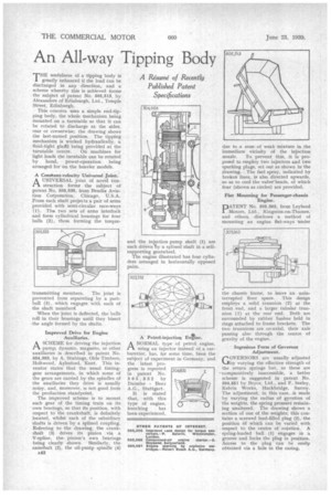
A Petrol-injection Entne.
ANORMAL type of petrol engine, using an injector instead of a carburetter, has, for some time, been the subject of experiment in Germany, and the latest progress is reported in patent No. 505.332 by Daimler Benz A.G., Stuttgart.
It is stated that, with this type of engine, knocking has been experienced. due to a zone of weak mixture in the immediate vicinity of the injection
nozzle. To prevent this, it is proposed to employ two injectors and two sparking plugs, set out as shown in the drawing. The fuel spray, indicatedby broken lines, is also directed upwards, so as to cool the valye'heads, of which four (shown.as circles) are provided.
Flat Mounting for Passenger-chassis Engine.
DATENT No. 505,363, from Leyland Motors, Ltd., Kingston-on-Thames, and others, discloses a method of mounting an engine flat-ways under
the chassis frame, to leave an uninterrupted floor space. This design employs a solid trunnion (2) at the front end, and a larger tubular trunnion (I) at the rear end, Both are surrounded by rubber bushes held in rings attached to frame brackets. The two trunnions are co-axial, their axis passing also through the centre of gravity of the engine.
Ingenious Form of Governor Adjustment.
OVERN ORS are usually adjusted L-lby varying the effective strength of the return springs but, as these are -comparatively inaccessible, a better scheme is suggested in patent No. 504,851 by Bryce, Ltd., and F. Seeley, Kelvin Works, Hackbridge, Surrey. The adjustment, in this case, is made by varying the radius of gyration of the weights, the spring pressure remaining unaltered. The drawing shows a section of one of the weights; this contains a screwed lead-filled plug (2), the position Of which can be varied with respect to the centre of rotation. A spring-loaded ball (1) engages in a groove and locks the plug in position. Access to the plug can be easily obtained via a hole in the casing.