65-B.U.T.
Page 149

If you've noticed an error in this article please click here to report it so we can fix it.
British United Traction, Ltd., 96 Piccadilly, London, W.1.
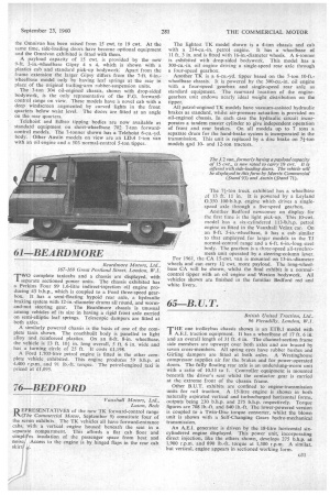
THE one trolleybus chassis shown is an ETB.1 model with A.E.T. traction equipment. It has a wheelbase of 17 ft. 6 in. and an overall length of 31 ft. 4 in. The channel-section frame side members are upswept over both axles and are braced by seven cross-members. All spring eyes have rubber bushes and Girling dampers are fitted at both axles. A Westinghouse compressor supplies air for the brakes and for power-operated doors. The fully floating rear axle is an underslung-worm unit with a ratio of 10.33 to 1. Controller equipment is mounted beneath the driver's seat whilst the contactor gear is carried at the extreme front of the chassis frame.
Other B.U.T. exhibits are confined to engine-transmission units for rail traction. A 15-litre engine is shown in both naturally aspirated vertical and turbocharged horizontal forms, outputs being 230 b.h.p. and 275 b.h.p. respectively. Torque figures are 708 lb.-ft. and 840 lb.-ft. The lower-powered version is coupled to a Twin-Disc torque converter, whilst the blown unit is shown with a Self-Changing Gears hydro-mechanical transmission.
An A.E.I. generator is driven by the 18-litre horizontal sixcylindered engine displayed. This power unit, incorporating direct injection, like the others shown, develops 275 b.h.p. at 1,900 r.p.m. and 890 lb.-ft. torque at 1,300 r.p.m. A similar, but vertical, engine appears in sectioned working form.


