


CA. Engine Without Injection Pump
Page 74
If you've noticed an error in this article please click here to report it so we can fix it.
A NOVEL design for a compression1—I ignition engine is shown in patent No. 733.928, by P. Stanwell, 24 Redbridge Lane, Wanstcad, London, E.11. No injection pump is used, the fuel being mixed with the ingoing air in the form of a crude spray.
Such a method used alone would, of course, give violent pre-ignition and the engine would probably fail to run, but the patent discloses a modified combustion system to render the scheme practicable.
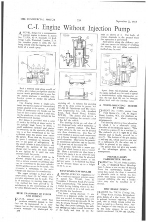
The drawing shows a single-cylindered two-stroke engine of conventional design adapted to the system, A simple form of carburetter (1) breaks up the fuel oil into a spray which is then fed, via the crankcase, to the cylinder in the well-understood manner.
The piston is provided with a nose (2) which, by fitting an upper cavity in the cylinder head, forms, in effect, a small additional cylinder and piston. In operation, on the upstroke, the mixture is at first compressed in the two cylinders until the piston nose enters the cavity. From then on, the pressure in space 3 continues to increase, but not to the point of self-ignition. In the small cylinder it does, however, and although the ignition of this small charge may be early, the main charge is not ignited by it until the nose emerges from the cavity.
A clearance of about 0.004 in. is allowed around the small piston, so that a certain amount of pressure rise can be transmitted to the main cylinder before ignition occurs in the latter. This promotes a turbulence in the main charge and improves its atomization.
The upper cylinder is fitted with a screw-down head (4) by' which compression adjustment can be made. This is of assistance in starting from cold. The method has been proved to be satisfactory in the construction of the so-called Diesels used in model aircraft.
BULK TRANSPORT OF FLOUR AND CEMENT
FLOUR, cement and other fine powders resemble liquids in that they can be 'transported in a tankwagon; but as they tend to pack, they cannot normally be discharged by
B34 draining off. A scheme for enabling this to be done comes in patent No. 733,346 (E. Oglethorpe and The Durarnin Engineering Co., Ltd., Standard Road, Park Royal Road, London, N.W.I0). The patent also covers a scheme for handling the material after it has left the vehicle. • The drawing shows an end view of the proposed body which resembles a_ tanker in general outline. The floor slopes down to the rear and is divided into three channels (1). The floor of each channel is porous and compressed air is blown through it from an underneath chamber. This keeps the powder in continuous agitation and so enables it to pour out of the nozzle (2).
The powder falls into a screw conveyor (3) which forces it into a venturi (4). Here a powerful air blast from a blower (5) ejects it in an airborne state from the exit. To this may be attached a hose or a trunking system at the delivery point. It is claimed that flour can be directly blown up to a height of 80 ft. or so.
CONTAINER-CUM-TRAILER
A SOUTH AFRICAN suggestion for rl a road-rail transport scheme comes in patent No. 733,691, from G. Tompkins, 9 Doveton Road, Parkstown West, Johannesburg. The patent shows a trailer having folding wheels so that it can be loaded on to a rail truck and yet provide low headroom.
The inner spring shackles (I) arc housed in a slideway whilst the outer ones are carried in swinging links (2); these normally point downwards. If the links be swung through 180 degrees, so that they then point upwards, the axle and springs are taken round the corner of the body and then lie on the ends as shown at 3. The body, of course, descends to the ground when this operation is performed.
Jack-screws along the slideway provide one means for raising or lowering the wheels, but any other convenient method may be used.
Apart from rail-transport schemes, the same method may be used to lower a double-decked cattle transporter so that the top deck (4) can be brought down level with the loading ramp.
A WHEEL-MOUNTING SCHEME BY FORD
PATENT No. 733,801, comes from Ford Motor Co., Ltd., 88 Regent • Street, London, W.1, and discloses an
improvement in wheel -mounting arrangements.
The drawing shows a front elevation in which I is a telescopic shockabsorber of the hydraulic variety. This is fixed by a screw (2) to a bracket (3). The stub-axle (4) is a tight fit in this bracket and is finally secured by a pin (5). The bottom of the pin carries a ball-end (6), which receives one end of a radius-arm (7), the other end of which is pivoted to the chassis.
The patent does not give any details of the advantages gained by the arrangement.
PHENOLIC-RESIN CARBURETTER FLOATS
PATENT No. 732,835, from Intermit, Ltd., 37 Bradford Street, Birmingham, 5, shows a new method of making floats for carburetters. Instead of using thin metal, the float is moulded in phenolic resin in halves, the two pieces then being cemented together. Internal stifferiing ribs and a needle valve may also be moulded in if desired.
DISC BRAKE DESIGN
PATENT No 728,376 (Girling Ltd., Kings Road, Tyseley, Birmingham) gives details of a disc brake. The disc is gripped between opposing friction pads, one of which moves whilst the other is held in a floating block. Further designs of disc brakes are shown by the same concern in two other patents numbered 728,709 and 728,942.