


Clutches 1
Page 74
If you've noticed an error in this article please click here to report it so we can fix it.
UNLIKE THE STEAM engine, the internal combustion engine, fitted to most commercial vehicles, does not produce much power until it is revolving at a fairly fast speed. When a vehicle is starting, the engine must be running at a high speed to provide the high torque necessary to move the vehicle. This fast revving engine has to be connected to the stationary drive leading to the road wheels. The connection must be made smoothly the drive between the that the vehicle does not leap away in a big jump and it is the clutch which has to provide this smooth take up of the drive.
The prime function of the clutch then, is to allow the driver to disconnect and to reconnect smoothly the driver between the engine and the gearbox at will, either when the vehicle is stationary or when changing gear and, of course, it must be capable of transmitting the full engine torque without slipping.
In the early days, a cone clutch, as illustrated in Figure 1, was used and because of the wedging action of the cone a low clamping force gave a high torque capacity. The cone was usually lined with leather, which had to be dressed at frequent intervals with Neatsfoot oil if the clutch was to retain its capacity to give a smooth take up of the drive.
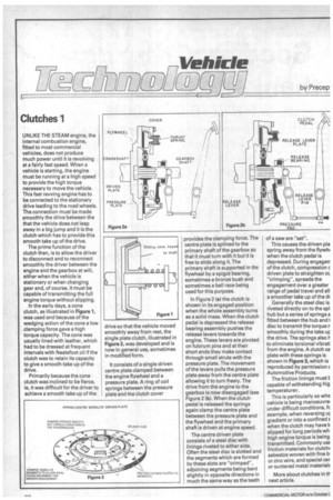
Primarily because the cone clutch was inclined to be fierce, ie, it was difficult for the driver to• achieve a smooth take up of the drive so that the vehicle moved smoothly away from rest, the single plate clutch, illustrated in Figure 2, was developed and is now in general use, sometimes in modified form.
It consists of a single driven centre plate clamped between the engine flywheel and a pressure plate. A ring of coil springs between the pressure plate and the clutch cover
provides the clamping force. The centre plate is splined to the primary shaft of the gearbox so that it must turn with it but it is free to slide along it. The
primary shaft is supported in ths flywheel by a spigot bearing, sometimes a bronze bush and sometimes a ball race being used for this purpose.
In Figure 2 (a) the clutch is shown in its engaged position when the whole assembly turns as a solid mass. When the clutch pedal is depressed the release bearing assembly pushes the release levers towards the engine. These levers are pivoted on fulcrum pins and at their short ends they make contact through small struts with the pressure plate. The movement of the levers pulls the pressure plate away from the centre plate allowing it to turn freely. The drive from the engine to the gearbox is now disengaged (see Figure 2 (b). When the clutch pedal is released the springs again clamp the centre plate between the pressure plate and the flywheel and the primary shaft is driven at engine speed.
The centre driven plate consists of a steel disc with linings riveted to either side. Often the steel disc is slotted and the segments which are formed by these slots are "crimped", adjoining segments being bent slightly in opposite directions in much the same way as the teeth of a saw are "set".
This causes the driven pla spring away from the flywho when the clutch pedal is depressed. During engagerT of the clutch, compression c driven plate to straighten oi "crimping", spreads the engagement over a greater range of pedal travel and all a smoother take up of the dr Generally the steel disc is riveted directly on to the spl hub but a series of springs a fitted between the hub and t disc to transmit the torque n
smoothly during the take up the drive. The springs also h to eliminate torsional vibrati from the engine. A clutch ce plate with these springs is shown in Figure 3, which is reproduced by permission c Automotive Products.
The friction linings must I capable of withstanding hig temperatures.
This is particularly so whe vehicle is being manoeuvre under difficult conditions, k example, when reversing uj gradient or into a confined s when the clutch may have to slipped for long periods wh high engine torque is being
transmitted. Commonly USE friction materials for clutch( asbestos woven with fine la, or zinc wire, and special cer or suntered metal materials
More about clutches in th next article.