


OIL RESISTANCE FOR CHECKING OSCILLATION.
Page 30
Page 31
If you've noticed an error in this article please click here to report it so we can fix it.
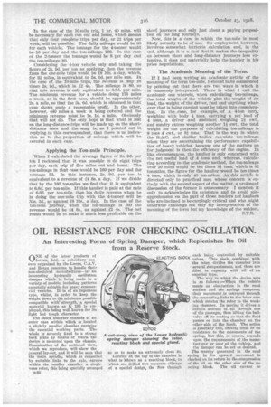
An Interesting Form of Spring Damper, which Replenishes Its Oil from a Reserve Stock.
0" of the latest products of Luvax, Ltd.—a subsidiary concern organized by the Lucas, C.A.V. and Rotax concerns to handle their non-electrical manufactures—is ' an interesting hydraulic oscillation damper which is being made in a variety of models, including patterns especially suitable for heavy commercial vehicles. It is of an ingenious type, whilst, in order to keep the weight down to the minimum possible compatible with strength, a special material known as 195 is employed, this being well known for its light but tough character. The shock absorber consists of an outer ease within which is located a slightly smaller chamber carrying the essential working parts. The whole is securely fixed to a strong back plate by means of which the device is mounted upon the chassis. Examination of the sectional view, which we reproduce, will show the general lay-out, and it will be seen that the mum spindle, which is connected by suitable links to the axle, carries within the smaller chamber a singlevane rotor, this being specially arranged
n46 eachbeing controlled by suitable
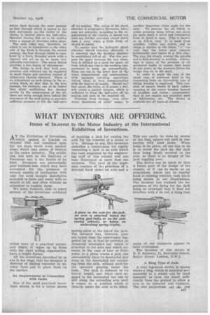
BLOck valve This block, _combined with the rotor, divides the chamber into several compartments, and these are filled to . capacity with oil of an especial type. The way in which the device acts is as follows :—When the vehicle meets an obstruction in the road surface and the springs compress, their movement is conveyed through the connecting links to the le'ver arm which rotates the rotor in the working chamber. In moving it drives a certain amount of oil through one of the passages, thus lifting the ball
valve off its seating so that the fluid • passes on into the chamber on the
• other -side of the block. The action is generally free, offering little Or rtO resistance to the movements of the spring, but this, of course, depends upon the requirements of the manufacturer or user of the vehicle, and the damper can be set as desired. The energy generated in the road spring in its upward movement is checked on its return by the compression of the oil on the other side of the reacting block. The oil cannot be
driven back through the same passage as that through which it passed in the first movement, as the orifice of the oilway is located above the hall-valve, therefore forcing this on to its seating, when a change of direction takes place.
The only other way, therefore, by which it can be transferred to the other side of the block is through the second passage, the flow through which is regulated by a finely threaded screw with a tapered end set so as to cause eonsiderable.restrictiou. The screw thread provides a fine degree of adjustment.
The design is such that both compression and rebound can be regulated to small limits and excellent control of suspension thereby obtained. There is an adjustment on each oilway in the reacting block, so that that in the first passage, for instance, can so be loaded that slight oscillations hre checked purely by the compression of the oil, there not being enough force behind the movement of the road spring to generate sufficient pressure to lift the ball-valve off its seating. The actionof the shtick absorber is progressive. Moreover, when once set correctly, according to the requirements of the vehicle, it should not need any further attention except about once a year, when a little fresh oil should be added.
To ensure that the hydraulic shock absorber should function efficientlY it is essential that the working chamber be maintained full of oil. For this purpose the space between the two chambers is utilized as a store for spare oil from which any loss in the working comPartment is made up automatically. Slots are cut in the lower face of the inner compartment and communicate with passages carrying non-return valves, these in turn communicating with the reserve oil supply. Should any loss occur, the rotor, as it passes a slot,will create a partial vacuum, which is sufficient to draw the ball-valve off its seating and suck in the required oil.
Freedom from leakage, even after many thousands of miles' usage, is another important claim made for the unit. To prevent the oil which is under pressure being driven out along the main shaft a novel and interesting form of gland is used. This is known as an SEA. ring. It is made front graphite, rubber and cotton, and in shape is similar to the letter "c" except that the lower part extends horizontally_and tapers to a thin edge. The ring fits closely around the spindle and is held securely in position. Advantage is taken of the pressure of oil generated inside to ensure that leaks do not occur, as the pressure forces the wedge ring on to the shaft.
In order to avoid the cost of the usual type of universal joint in the connecting links an interesting type of tilting bearing is employed. This consists of square blocks of hard rubber carrying at the centre brushes formed of graphite and cotton ; consequently they do not require any attention such
as lubrication, etc. The device is available for-all types of chassis. .