


A NEW FAST LI(
Page 16
Page 17
Page 18
Page 19
If you've noticed an error in this article please click here to report it so we can fix it.
) CWT. CHASSIS
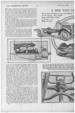
NTO make of chassis has won a better name for allill round reliability than the Albion, and one proof of this statement is the -large overseas trade which is enjoyed by the Albion Motor Car Co., Ltd., Scotstoun, Glasgow. One reason for this is that before the issue of any new type for sale it receives a lengthy and strenuous test—we will not say to destruction, because that would be to set the tester a problem almost too great to be overcome.
These remarks apply with full force to the M40, 20-36 h.p., 30-cwt model which has just been placed upon the market. Test machines have been tried out for a distance of 140,000 miles more than fully laden. There is also an overseas edition of this model which is known as the M41, the main difference being that, to permit a larger ground clearance, the worm is above the _axle.
Our personal test of the new model quickly showed us that it will fully uphold the reputation of its maker. Although of extremely sturdy construction, it is not heavy, the weight being approximately 291 ewt., and it will carry its full load of 30 cwt. with a body allowance of 10 cwt., the tax being 126 this year and 125 next year.
Our test run was made in Glasgow and its environs, where there are many redoubtable hills. We made stops on each brake separately, going up and down Gardner Street, which has a gradient of I in 6. There was no difficulty whatever in getting away after the stop during the ascent. Surprisingly long gradients were taken easily on top gear, and, on the level, speeds up to 45 m.p.h. were reached. We ourselves were driving for some time at 42 m.p.h., and found the laden chassis quite as easy to control as a private ear, and with that excellent acceleration which is so advantageous in traffic and which is usually the prerogative of the car. At the higher speeds the vehicle held to the road in an excellent manner ; there was no dither of the rear wheels, whilst the engine could hardly be heard. Incidentally, the power unit will run up to 3,000 r.p.m. without any risk of damage, and the gearing is such that it is running at 2,250 r.p.m. at 35 m.p.h., and at 1,280 r.p.m. at 20 m.p.h.
It may be as well now to give the gear ratios. That of the axle is 61 to 1 in the M40, and 61 to 1 in the overseas model, whilst the gearbox ratios are: third, 1.58 to 1; second, 2.04 to 1; first, 4.13 to 1; reverse, 3.50 to 1. Under the best conditions, fully laden, 20.15 m.p.g. have been obtained, but this mileage naturally depends upon the conditions of operation and the speed.
The standard tyre equipment is 33 ins. by 5 ins, at the front, and 34 ins. by 7 ins, at the rear, and the price, with a spare wheel equipped with a super-cushion solid tyre, is £365, this including a 5-lamp 12-volt lighting set, electric horn and speedometer, whilst an electric starter and tyre pump can be fitted at an extra cost. This chassis will be supplied complete with a B32 choice of three standard types of body, viz., a plain platform, a lorry with hinged sides, and a van, the prices of the complete vehicles being f415, 1420 and f440 respectively, in grey finish, ex works.
The main dimensions are: wheelbase, 10 ft. 9 ins.; track, 4 ft. 9 ins..; ground clearance, 71 ins; diameter of turning circle, 43 ft.; frame height (laden), 2 ft. 21 ins, for the home model, and 2 ft. 21 ins. for the overseas model; overall length, 16 ft. 61 ins.; overall width, 5 ft. 9 ins.
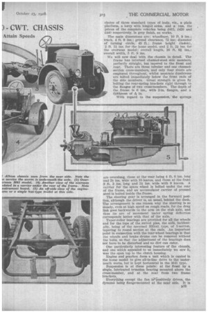
We will now deal with the chassis in detail. The frame has inturned channel-steel side members, perfectly straight, but tapered to the front and rear. There are three tubular and one channelsection cross-members, and only four rivets are employed throughout, whilst separate dumhirons are bolted immediately below the front ends of the side members. Great strength is given by bolting the rear-spring brackets right through to the flanges of two cross-members.• The depth of the frame is 6 ins., with 2-in, flanges, and a thitkness of -Pe in. With regard to the suspension, the springs are overslung, those at the' rear being 4 ft. 6 ins, long and 2i ins, wide with 10 leaves, and those at the front 3 ft. 3 ins, long and 2i ins, wide with 9 leaves. A carrier for the spare wheel is bolted under the rear of the frame, and an accumulator carrier of pressed steel is bolted inside the frame.
The steering gear is arranged in the forward position, although the driver is, as usual, behind the dash. The arrangement is one reason why the steering is so steady, even at high speed on rough roads, for the drag link goes backwards to the arm on the stub axle, and thus its arc of movement under spring deflection corresponds better with that of the axle. Taper-roller bearings are provided for all the wheels and for the tops of the swivel pins, the axle, incidentally. being of the reversed Elliott type, of I-section, tapering to round section at the ends. An important point in connection with the rear-wheel bearings is that the wheels and brake drums can be removed without the hubs, so that the adjustment of the bearings does not have to be disturbed and no dirt can enter.
One particularly interesting feature of the chassis, and one which appealed to us immediately we saw it, was the open top to the clutch housing.
Engine and gearbox form a unit which is canted in the home model to give all-in-line drive to the underneath worm, but is kept horizontal in the M41 type.
Suspension is at three points: at the front by a single, lubricated trunnion bearing mounted above the cross-member, and at the rear from two frame brackets.
Everything except the fan igr-positively driven, the dynamo being flange-mounted at the near side. It is B33
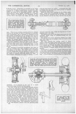
a 12-volt C.A.V. Cross-drive is provided to the pump at the near side and the magneto at the off side. The magneto is a Simms with rubber vernier coupling, whilst the pump is of centrifugal pattern with the Albic.n-Murray patent gland, consisting of a screwed collar carried on threads cut on extensions of the casting above and below the collar, the sides being
open. , There is an auxiliary dynamo drive by enelosed chain to the off side, so that if a governor be specified (and, incidentally, this is included as standard on the M41 'Model)" the dynamo can be changed over and the governor driven at the near side SQ that it is close to the carbnretter.. This also .permits using. a bus type dynamo for special lighting. A V-link belt with expanding pulley adjustment is utilized for the fan.
The four cylinders, which are cast en bloc with the crankcase, have a bore of 3i. ins, and a stroke of 41 ins.; they have side valves and a detachable head. A dip rod is conveniently situated. toWards the rear of the off side; The lubricant is force-fed 'throughout, but there is only one external pipe—that leading to the dial pressure 'gauge on the dash. The relief valve is mounted over the timing gear and the surplus oil runs over the gears and back to the sump, the actual quantity when the engine is running being 200 gallons per WI*. •A helical-pinion submerged oil pump is driven i AI the
camshaft. It is situated at the rear in a mnall detachable sump covered by filter gauze. The inlet valves are of the masked Ricardo pattern in which the cams give a higher and longer lift, and a rapid effective opening is obtained. Nickel steel is used for the inlet valves and nickel-chrome steel for the exhaust. On the cylinder head are two special lifting studs; the forward stud balances the engine only and the rear stud the engine and gearbox unit, thus facilitating slinging the engine when removing it from or replacing it in the chassis. With unskilled labour, the engine and gearbox unit has been removed from the chassis in 50 minutes. Incidentally, the engine weighs approximately 5 cwt. Twenty-four nuts are utilized to hold the cylinder head. The combustion chambers are of the high-efficiency pattern with the sparking plugs n34 over the swell above the valves. A siamesed inlet pipe is utilized and this has been found greatly to improve the mixture distribution.
There are three main bearings for the drilled crankshaft. These are of exceptional strength. The front journal is 2 ins, diameter and 2-tins, long, the centre 21 ins, diameter and 21 ins, long, and the rear 21 ins.
diameter and 3 ins, long, whilst the big-ends are 21 ins. " diameter and 2 ins. long.
The timing gears are of the single helical pattern, the camshaft pinion being of phosphor-bronze and the others of steel.
The pistons are of the aluminium B.H.B. type with four wide rings, and the gudgeon pins are fixed in the connecting rods.
The total capacity for cooling water is three gallons, whilst the engine sump holds two and a quarter gallons of oil. Incidentally, in the filtration of the oil, it is sucked up through the filter, thus making the gauze self-cleaning. The water pipes are flange-fitted to the radiator, a feature which we have often recommended.
Carburation is effected by a Zenith instrument and it has been considered advantageous to provide very thorough exhaust jacketing of the inlet pipe, there being a -I-in, hole between this jacket and the exhaust manifold. A novel feature is the provision of a special con fleeting pipe from the bottom of the jacket to the silencer, so that the gases actually flow through the jacket, which does not tend to become choked with carbon.
It was interesting to find that there are no tappets in the strict sense of the word. When the two cover plates are removed, fingers pivoted close to the openings can be discerned. These stretch under the valve stems, where adjustable pins are provided, and branch downwards into direct contact with the cams.
The flywheel is a steel forging and upon it are marks to assist the timing, there being an indicator at the rear of the cylinder block.
The petrol is supplied through a Petrollex flexible pipe clipped at two points. There are two fuel filters, one in the feed system and the other in the base of the carburetter.
In the case of the M40 model, the flange on the inlet pipe is set at a slight angle to bring the carburetter vertical; also in each vehicle the carburetter is set across so that gradients do not affect the level in the jet.
The bonnet is in four pieces with flap-over binges which prevent the entry of water, and a clip for an oil gun is provided at the bonnet side of the dash. The bonnet sides have Special clips which fit over bolts on the dash when it is required to support them in the up position.
We illustrate the simple single-plate clutch, in which it will be noticed that the plate is belled in, so making the clutch exceedingly compact. It has direct withdrawal gear and a novel type of clutch brake. As the pedal 'moves forward, it lifts a cup at the base of a compression spring, and the rod carrying this spring transfers the motion to a short lever mounted on a shaft passingthrough the side of the -gearbox, this shaft carrying a bronze shoe which makes frictional contact with a smooth portion of one of the layshaft pinions ; as if rims in oil, the wear should be negligible and the action is, of course, very smooth.
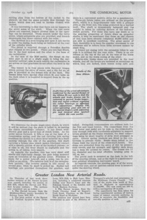
AS regards the gearbox, this has very short stiff shafts and right-hand change, the gate being mounted upon an extension of the gearbox cover. Provision is made for a power take-off, and a pump can be prosided as an extra. The selector lock is of the swingingfork pattern. The reverse pinion is idle except on second gear, when its shaft is picked up. Radial ball bearings ore provided throughout the gearbox, and there is a convenient positive drive for a speedometer.
Three-ply fabric joints are utilized on the propeller shaft, which is a large-diameter tube with a plunger joint at the front end, this being protected by a leather muff. The shaft is dynamically balanced and the weight is taken by centring devices of the ball-andsocket pattern. For those who have any doubt as to the wearing properties of fabric discs on propeller shafts, it may be mentioned that those on one chassis of this type have already completed 40,000 miles and are still in excellent condition. The great secret of their durability is to keep the angular movement to the minimum and to relieve them from stresses caused by shaft fling.
A forged pot casing with the extension tubes in one with it is utilized for the rear axle. There is an air release at the top of the pot in the case of the home model, and on the worm casing of the other.
Side-by-side brake shoes are provided in the rear wheels, and all the levers are mounted on serrations on which they are locked, their bosses being split anti
bolted. Swing-link compensators are utilized both for the foot and hand brakes. The connections from the hand lever and pedal are by rods to the cross-shafts, then through rods with turnbuckle adjusters to support levers pivoted on the frame brackets, the final connections being by short lengths of strip steel arranged in pairs. Grover spring washers are fitted to the Connections to prevent rattle. Brake stops bolted to the frame limit the travel of the cross-shaft levers. The shoes are protected from the entry of dirt by pressedsteel covers, and for strength and rigidity each drum has a deep rib around its centre. The drums are 17 ins, diameter and the total effective braking area is 182 so. ins.
The petrel tank is mounted on the dash to the left of the steering column, and at the right is a particularly neat polished aluminium instrument board. As regards controls, the steering gear is of the worm and sector type, and an ignition-control lever is mounted under the steering wheel.