


PNEUMATIC BRAKE OPERATION.
Page 30
If you've noticed an error in this article please click here to report it so we can fix it.
A Résumé of Recently Published Patenti,
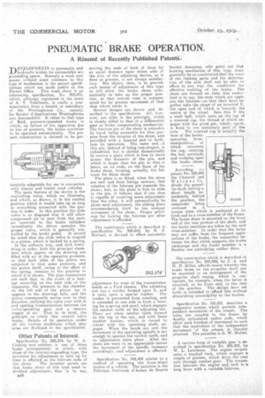
TIEVgLOPMENTS in pneumatic and hydraulic brakes for automobiles are proceeding apace. Scarcely a week now passes without some reference to this type of mechanism in the patent specifications which are made public at the Patent Office. This week ,there is an interesting specification, No. 203,071, which, although registered in the name of A. V. Tomlinson, is really a communication from a. branch or subsidiary ef the Westinghouse -Co., namely, La Societe d'Applicatiens Westinghouse mix Automobiles. It refers to that type of fluid, pressure-operated brake in which, on failure of the apparatus clue to loss of pressure, the brake continues to be operated automatically. The present construction is claimed to be par ticularly adaptable for use in connection with tractor and trailer road vehicles.
The main feature of the device is the controlling valve, which we illustrate, and which, as drawn is in the normal position which it would take up so long as everything connected with the gear was in order. In this position the slide valve is so disposed that it will allow compressed air to pass from the main air 'reservoir to the brake cylinders immediately the driver operates the proper valve, which is generally con trolled by the brake pedal. It should be noted that the slide valve is coupled to a piston, which is backed by a spring..
In the ordinary way, and with everything in order, both the principal chambers which appear on the drawing are filled with air at the operative pressure, so that both sides of the piston are subjected to that same pressure, and the piston itself, owing to the effect Of the spring, remains in the position in which it is shown. The pipe connect-ions are such that, in the event of a leakage occurring on the inlet side of -the epparatus, the pressure in the chamber on the left side of the piston (as it appears in the drawing) falls, end the piston consequently moves. over in that direction, carrying the valve over with it and opening communication between the valve-operating gear and a reserve supply of air. That is, in brief, the principle on which this control val-e works. Details of its operation under all the various conditions which may arise are disclosed in the specification.
Other Patents of Interest.
Specification No. 203,574, by W. A. Cocking and another, is one of those brake arrangements in which, with shoes of the internal-expanding type, the provision for adjustment to take up for wear is effected at the fulcrum ends of the shoes. The inventor points out that brake shoes of this type need individual adjustment.; that is to say, 848 moving the ends of both of them by an equal distance upon either side of the axis of the adjusting device, as is dune at present, is not always satisfaetory. His object, then, is to provide such means of adjustment of this type as will allow the brake shoes automatically to take up the proper position, so that uneven wear is compensated for by greater movement of that shoe which needs it.
Several designs are shown and de'scribed in the specification. All, however, are. alike in the principle, which is closely allied to that of a differentiel gear or brake compensating mechanism. The fulcrum pin of the shoes is rotatable by hand, being accessible for that purpose from the exterior of the drum, and 'provided with a squared end to facilitate its operation. The inner end . of this pin, instead of being cam-shaped, is cylindrical, but. is slotted diametrically to receive a plate which is free to move across the diameter of the pin, and which is larger than the phi, so that it bears, on its ends, on the faces of the brake shoes, forming, actually, the fulcrum for those shoes.
The plate is so fitted, when theshoes are new and their, linings unworn, that rotation of the fulcrum pin expands the shoes ; but, as the plate is free to slide in the pin, it follows that if one shoe is capable of receiving more adjustment than the other, it will automatically be given such adjustment, the sliding plate accommodating itself to the unequal movement of the shoes. Proper proVision for locking the fulcrum pin after adjustment. is afforded.
The contrivance which is described inn specification No 203,019, by B. J. Michael, is devised to effect automatic
adjustment for wear of the transmission bands on a Ford chassis. The adjusting nut has a ratchet formed upon it, and it rests upon a special washer. The washer is prevented from rotating, and is extended at one side to form a housing for a spring and pawl, which engages the ratchet teeth on the adjusting nut. Thera are other ratchet teeth formed On the top of the nut, and with these another washer, which is forced to rotate with the operating shaft, engages. When the bands are new the movement of the operating spindle is not. enough to operate the ratchet teeth; and no adjustment takes place. After the shoes are worn to an appreciable extent the movement of the spindle increases accordingly, -and adjustment is effected.
Specification No. 192,409 relates to method of operating._ the froet-wheel brakes of a vehicle. The patentee is the Fabrique Nationale d'Armes de Guerra
Societe _Anonym°, who point out that, braking mechanfins of this type must generally be so constructed that the weer of the rubbing parts and the deformation of the axle shall not be able to effect in any way the conditions for effective working of the brake. The shoes are formed on their free ends— that is to say, the ends which site opposite the fulcrum—so that their faces. together take the shape of an inverted V, the open end of which is towards the centre of the wheel. Into this V fits a steel ball, which rests on the top of a screwed cap, the thread of which engages with the pivot pin, which, again, is fixed to the stationary part of the axle. The screwed cap is actually the boss of the brakeoperating lever, manipulation of which unscrews the cap, carrying the ball outwards and wedging open the brake .shoe.
According t o •
patent No. 195,045 ' the Chenard wed Walcl The construction which is described in specification No. 203,500, by J. A. and W. D. Miller, affords means whereby-the. brake drum on the propeller shaft. can be mounted in an enlargement of the propeller shaft casing, which is convenient, for example, when the latter is attached, at its front end, to the rear of the gearbox. The design here set forth, is intended to afford this without diminishing accessibility to the brakes, Specification No, 181,031 describes a suspension system which permits independent movement of the wheels. The axles are coupled to the fra.me by doubly articulated radius rods, which allow such freedom of movement to each that the equivalent, of the independent movement of the \wheels is thereby attained. The patentee is G. W. Muller. A curious -form of variable gear jade• scribed in specification No. 21)3,422, by W. L. Lawrence. . The engine reciprocates a, toothed rack, which engages a couple of pinions, which drive the rear axle through ratchet gear. The connection between the engine and rack is a long lever. with a variable fulcrum.Tags