


A Non-sticking Magnetic Clutch
Page 72
If you've noticed an error in this article please click here to report it so we can fix it.
AGNETIC clutches employing al powdered iron are prone to a defect called "sintering," that is, the ferromagnetic particles tend to form lumps and impair the action. Patent No. 758, 621 describes a special powder
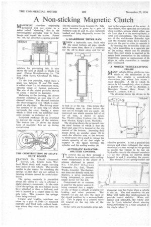
mixture for preventing this; it also shows the type of clutch in which it is used. (Eaton Manufacturing Co., 739 East 140th Street, Cleveland 10, Ohio, U.S.A.) To the iron particles, which have a grain size between 50 and 300 mesh, is added about 2% of aluminium oxide, chromic oxide or barium carbonate. The size of the added particles should be about I micron in diameter.
Referring to the drawing, the driven member comprises an iron ring (1) of channel section. The channel contains the electromagnetic coil which is energized via slip rings. The driving member consists of an iron ring (2) which surrounds the rotor, leaving a space which is filled with the solidified magnetic powder as indicated at 3.
Labyrinth packings (4) are provided to prevent the escape of the mixture. The broken line (5) shows the closed loop of magnetic flux set up during eneraization THE CONSTRUCTION OF HEAVYDUTY BOGIES
• PATENT No. 758,643 (Scammell Lorries, Ltd., Tolpits Lane, Watford .West) deals with bogies carrying four pairs of twin wheels. The novelty resides in the means for attaching the springs so that they are not subject to twisting stresses caused by cross-articulation.
The spring assembly is journalled about th-e centre (I) and is allowed a slight sideways movement. At the ends (2) of the springs, the two bottom leaves have attached to them a ball-end, and this is housed in a socket fixed to the axle tube. This prevents the springs from being twisted.
Torque and braking reactions are taken by a pair of links (3) mounted centrally and fitted with resilient bushings where they meet the axle tube (4) c32 and the central frame bracket (5). Sideways location is given by a pair of Panhard rods (6 and 7), also resiliently bushed and lying diagonally across the assembly.
WHEN a hydraulic ram, fitted with the usual bottom oil pipe, stands idle for some time, there is a tendency for the oil' to drain away and for air to eak in at the top. This means that air-bleeding must be done before the ram can be brought into use again. An improved ram which remains full of oil for all time, is shown in patent No. 756,031 (Alley Trailers, Ltd., Burnham Market, King's Lynn, Norfolk).
The drawing shows the proposed ram, the chief feature of which is that the fluid inlet pipe (1) is located at the top instead of the bottom. Incoming fluid passes down an annular space (2) to reach the effective area at the bottom. A bleed-screw (3) is used to release the minute quantity of air that might be trapped in the space between the cylinder and the sealing washer (4).
AUTOMATIC RADIATORSHUTTER CONTROL PrO control the air flow through a
radiator in accordance with coolingwater temperature is the object of a scheme disclosed in patent No. 758,847 (Clayton Dewandre Co., Ltd., Titanic Works, Lincoln). The thermostat does not directly work the shutters, a servo mechanism being interposed, to provide ample power for the job.
Compressed air or vacuum is used for the power source, it being assumed that a supply of one of these is already availab e for braking and other purposes. The shutters (I) are put into the open or the closed position by a servo-cylinder (2). This is piped to a control valve (3) located on the top tube of the radiator.
In the valve are bi-metallic strips sub
ject to the temperature of the water. A they deflect, they open one air valve an close another, actions which either pas air from pipe 4 to the servo-cylinder, o open it to atmosphere. The valves uset are of the well-known Schrader type and the bi-metal strips have merely t• press on the pin in order to operate it By housing the bi-metallic strips am the valve assemblies in a separate par of the casing, which can be detachel from that part which is inserted in th■ upper hose connection to the radiator inspection, repair or replacement of thl strips or valve assemblies is consider ably facilitated.
A MOBILE VEHICLE-LIFTING FRAME
MANY vehicle-lifting platforms hay. much of the mechanism in till centre; this creates a considerabll obstruction just where free access i most desirable. A lift in which th+ centre is left completely clear is show' in patent No. 757,746 (J. Randall, E Georgian House, Bury Street, St James's, London, S.W.I).
The drawing shows the device in flu effective position. It has a parallel-link motion and when collapsed, the upper members are near enough to the ground to enable the vehicle to be run on. Hydraulic rams in the channel members (1) do the lifting, an electric pump housed in end 2 providing the power.
The wheels (3) are spring-loaded and
disappear into the frame when a vehicle is run on. The end members (4) are fitted with trellis-like reinforcement to provide lateral stability. When collapsed and unloaded, the whole unit can be freely wheeled about, steering being performed by a tiller attached to the single wheel 5.