


Correct Wheel Alignment Cuts Tyre Costs
Page 44
Page 45
If you've noticed an error in this article please click here to report it so we can fix it.
NO doubt some operators nurse the opinion that far too much is made of the need for preserving a fine limit of alignment of front wheels. Few, however, can fail to treat seriously abnorrnal tyre wear, of which ane of the direct causes can often be traced to an incorrect setting of the front wheels.
It is the usual practice to arrange for an overall toe-in of I in., but the vehicle maker's recommendation should be consulted. Leyland Motors, Ltd., has for a long time advocated that the front wheels be set parallel to one another, the company's experience being that tyre wear is much less than when the usually accepted *-in. toe-in is given.
The purpose of toe-in is to allow for slackness in the steering ball joints, so that, under running conditions, the front wheels, which tend to spread, will assume a parallel relationship.
Wheels will sometimes tend to toe-out when the vehicle is travelling, although a static test may fail to reveal the cause. In such circumstances it may be found that the inclination of the king-pins is such that a line drawn through the centre of their axes would, if extended, fall inside the centre of contact of the tyres with the road.
1 do not, however, propose to discuss the technical aspects of toe-in and toeout, so much as to describe the use and application of the various types of wheeltlignment gauge available through the A34 aid of which such faults as may exist can readily be corrected.
In most cases, measurements to a degree of accuracy of 1/64 in. can be obtained. Such a fine reading for frontwheel alignment might seem to be unnecessary until it is realized that with
only in. inaccuracy in alignment, a tyre is dragged sideways for about 8 yds. in every mile.
In view of the need for obtaining fairly accurate readings, it will be obvious that little purpose will be served in testing for faulty wheel alignment if there be excessive play in the stab-axle bearings or steering linkages. All such faults must be corrected before applying a wheel-alignment gauge.
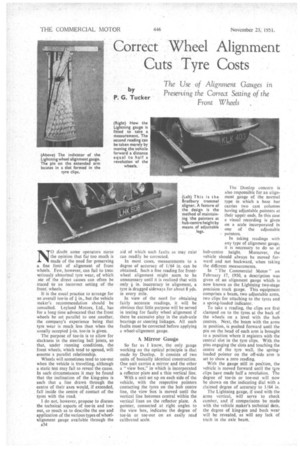
A Mirror Gauge
So far as I know, the only gauge working on the optical principle is that made by Dunlop. It consists of two units of. basically identical construction. One unit carries a mirror and the other a "view box," in which is incorporated a reflector plate and a thin vertical line.
With a unit set up on each side of the vehicle, with the respective pointers contacting the tyres on the hub centre line, the view box is moved until the vertical line becomes central within the vertical lines on the reflector plate. A pointer, connected at right angles to the view box, indicates, the degree of toe-in or toe-out on an easily read calibrated scale.
In taking readings with any type of alignment gauge, it is necessary to do so at hub-centre height. Moreover, the vehicle should always be moved forward and not backward, when taking the different measurements.
In The Commercial Motor" on February 17, 1950, a description was given of an alignment gauge which is now known as the Lightning two-stage precision track gauge. This equipment comprises a beam, two adjustable arms, two clips for attaching to the tyres and a spring-loaded indicator.
To take a reading, the clips are first clamped on to the tyres at the back of the wheels on a level with the hub centres. Next, the beam with the arms in position, is pushed forward until the pin on the head of each arm is brought to a position where it registers with the central slot in the tyre clips. With the pins engaging the slots and touching the centre of the tyre wall, the springloaded pointer on the off-side arm is set to show a zero reading.
With the gauge still in position, the vehicle is moved forward until the tyre clips have made half a revolution. The degree of toe-in or toe-out will now be shown on the indicating dial with a claimed degree of accuracy to 1/64 in.
The Lightning gauge, if used with the arms vertical, wilt serve to check camber, arid if comparisons be made with the vehicle maker's technical data, the degree of king-pin and bush wear will be revealed, as will any lack of truth in the axle beam.
Consistent with efficiency, the P.C.L. gauge has been reduced to the simplest possible lines.. The base bar, which consists of three tubestelescoping one into the other, carries two vertical arms on which are mouated the pointers. As the base bar is carried on two twowheeled bogies, the arms on which the pointers are mounted remain vertical during the measuring operation.
In the Britool Micro gauge, the pointers are provided with screw adjustment, so that a fine degree of accuracy in the readings can be obtained. The basic structure consists Of two widebased standards which carry the microscrew pointers. The movement of one of these adjustable pointers is recorded on a dial so that the difference between a 'reading 'taken on the riM.at.,.. the' back of-•the:wIteel with the dial peinter•set at zero, and a • rim reading taken... at the front of the w-heel.after the pointer. has been adjusted, will• represent the
included toe-in or toe-Out. •
ASimple Design . .
The Bradbury trammel-•aligner is of the simplest possible design,. consisting of a Main bar carrying two arnis provided with integral screw cramps. At their outer ends these arms carry the feelers or pointers, which can be freely moved in their mountings and secured against subsequent movement. As it is necessary to take the measurements at a point on a level with the centre of the wheel hub, adjustable supports are provided to keep the pointer arms at the desired level.
There are many features incorporated in the Churchill 95B track gauge which entitle it to be placed in a class of its own. It is exceptionally well made and all the moving parts are mounted On ball bearings. The possibility of inaccurate readings being obtained through the effects of friction. has been eliminated by adopting what is termed a " floating beam."
This beam, which bears the pointer arms, is carried on the main base-beam, which, in its turn, is mounted on two two-wheeled bogies. Readings arc recorded on a large open-faced, dial, the pointer scale being equal to a length
of 12 ins, to give a plus or minus reading of /
In the Weaver indicator there is a free-moving plate mounted on rollers, and to obtain a reading the vehicle is either rolled or driven over the plate;
an immediate recording is given on the indicator.' In conjunction with • this indicator is -a: gauge Which registers the number of feet. per 'mile that the .tyres are dragged sideways if the wheels be misaligned.
Reasonable Cost
Wheel-alignment cheeks should be included in all maintenance schedule's. this applying particularly to vehicles used on rough service. The prices of wheel.alignment gauges vary from a few pounds to £20 or so, and whilst the cheaper forms give excellent service. the higher-priced article usually carries refinethents which tend towards more simple application, and the maintenance of a high degree of accuracy over long periods of use, •
The names, and addresses of the makers of the equipment mentioned in this article are as folloWs:—Dunlop Rubber Co., Ltd., Fort Dunlop, Birmingham, 24; Elms Garage, Red nail Road, Birmingham (Lightning track gauge); Pneumatic Components, Ltd„ Sheffield (P.C.L.); Jenks Bros., Ltd.. Wolverhampton (Britool Micro); Joseph • Bradbury and Sons, Ltd., Braintree (Bradbury); V. L. Churchill and Co., Ltd., Walnut Tree Walk, Lambeth North, London, S.E.11 (Churchill); Weaver Manufacturing and Engineering Co.. I.td.. Magna Works, Bedford.