


Modified Wedge-operated Brake Mechanism
Page 36
If you've noticed an error in this article please click here to report it so we can fix it.
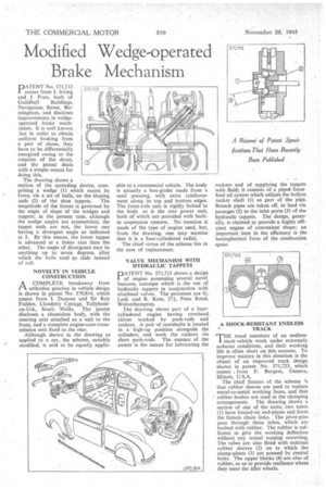
A &store of Patent Specifications That Have Recently Been Published PATENT No. 571,712 I comes from J. Irving and J. Pratt, both of
Guildhall Buildings, Navigation Street, Birmingham, and discloses improvements in wedgeaperated brake mechanism. It is well known that in order to obtain uniform braking from a pair of shoes, they have to be differentially energized owing to the rotation of the drum, and the patent deals with a simple means for doing this.
The drawing shows a section of the spreading device, comprising a wedge (1) which exerts its force, via a set of balls, on the sloping ends (2) of the shoe tappets. The magnitude of the forces is governed by the angle of slope of the wedges and tappets; in the present case, although the wedge angles are symmetrical, the tappet ends are not, the lower one having a divergent angle as indicated at 3. By this means, the lower tappet is advanced at a faster rate than the other. The angle of divergence may be anything up to seven degrees, after which the balls tend slide instead of roll.
NOVELTY IN VEHICLE CONSTRUCTION
PIA COMPLETE breakaway from orthodox practice in vehicle design is shown in patent No. 570,814, which comes from I. Duncan and Sir Roy Fedden, Llandetty Cottage, Tallybonton-Usk, South Wales. The patent discloses a chassisless body, with the steering axle attached as a unit to the front, and a complete engine-cum-transmission unit fixed to the rear.
Although shown in the drawing as applied to a car, the scheme, suitably modified, is said to be equally applic
able to a commercial vehicle. The body is actually a box-girder made from a steel pressing, with extra reinforcement along its top and bottom edges. The front-axle unit is rigidly bolted to the body, as is the rear power unit, both of which are provided with builtin suspension systems. No mention is made of the type of engine used, but, from the drawing, one may surmise that it is a four-cylindered radial.
The chief virtue of the scheme lies in the ease of replacement.
VALVE MECHANISM WITH HYDRAULIC TAPPETS
P ATENT No. 571,715 shows a design 1 of engine possessing several novel features, amongst which is the use of hydraulic tappets in conjunction with overhead valves. The patentees are G. Leek and R. Rose, 271, Penn Road, Wolverhampton.
The drawing shows part of a foitrcylindered engine having overhead valves worked by push-rods and rockers. A pair of camshafts is located in a high-up position alongside the cylinders, and work the rockers via short push-rods. The essence of the patent is the means for lubricating he rockers and of supplying the tappets with fluid; it consists of a piped force feed oil system which utilizis the hollow rocker shaft (1) as part of the pipe. Branch pipes are taken off, to lead via passages (2) to the inlet ports (3) of the hydraulic tappets. The design, generally, is claimed to provide a highly efficient engine of convenient shape; an important item in the efficiency is the hemispherical form of the combustion space.
A SHOCK-RESISTANT ENDLESS • TRACK THE tread members of an endless' track-vehicle work under extremely arduous conditions, and their working life is often short on this account. To improve matters in this direction is the object of an improved track design shown in patent No. 571,723, which comes from F. Burgess, Geneva, lllinois, U.S.A.
The chief feature of the scheme ;s that rubber sleeves are used to replace metal-to-metal working faces, and that rubber bushes are used in the clamping arrangements. The drawing shows a section of one of the units; two tubes (1) have brazed-on end-plates and form the female chain links. The pivot-pins pass through these tubes, which are bushed with rubber. The rubber is sufficient to give the working deflection without any actual turning occurring. The tubes are also fitted with external rubber sleeves (2) on• to which the clamp-plates (3) are pressed by central bolts. The upper blocks (4) are also of rubber, so as to provide resilience where they meet the idler wheels.