A Self-weighing Body for Lorries
Page 60

If you've noticed an error in this article please click here to report it so we can fix it.
A METHOD of ascertain
ing the weight of the load on a vehicle by means of a built-in apparatus is shown in patent No. 416,063 by L. Corper, 3, Oakville Mansions, Grosvenor Square, Southampton, and R. A. C. Knop, 40, Oxford Street, Southampton. The apparatus calls for the mounting of the body on four hydraulic plungers which are connected by piping to a central point, where a handpump, oil-tank, and pressure gauge are located.
In operation, when it is desired to weigh the load, the.hydraulic plungers are raised by the hand-pump, after which a reading is taken of the pressure gauge; this will be proportional to the total weight. A valve is described. the duty of which is to connect the gauge to any one of the plungers separately, the object being, it is stated, to obtain four separate readings in cases where the load is badly distributed. In these circumstances the single reading should still be correct, but there are other obviobs advantages.
patent No. 417,482 by E. G. Harrington, Sackville Works, Hove, Sussex. As will be seen from the drawing, the passenger seats are each arranged to be a little higher than those immediately in front, so that the total depth of space gained appears at the rear of the vehicle as an appreciable amount in a compartmerit (1). This space may, if necessary, be continued below and outside the chassis members, forming panniers, whilst still more room may be obtained by constructing similar compartments (2) having doors in the sides. In addition the specification describes the methods and materials used in the construction, and the means for gaining access to the two luggage cornpartneents.
B46 Injection-pump Progress.
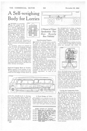
PATENT No. 417,541 shows a modification to injection pumps that is intended to ensure a good fit between plunger and cylinder, even after the plunger has bad considerable wear. The patentee is P. Hansen, Svejgaardsvej 3, Copenhagen, Denmark. The pump is made on the usual lines, that is, oil enters the chamber via pipe (1) and is subjected to pressure by' the rising plunger, the injection period terminating when the triangular recesses (3) uncover the supply parts.
The novel point is the provision of a bore (2) in the centre of the plunger, its size being approximately half that of the outer diameter. The object of this is to allow the working diameter to be expanded by the oil pressure and thus at all times to preserve a good fit. The principle is the same as that of a leather cup-washer, as used in air pumps.
No. 417,523 by R. V. Gray, of Dunbar Automobile and Engineering Co., Dunbar, Scotland. The valve is primarily of the mushroom type, but operates by being rotated instead of being made to lift, ports being covered and uncovered by the rotary. motion. A special feature is the slight lifting of the valve from its seat preparatory to its being turned.
The drawing shows a further development in which an inlet and an exhaust valve are arranged one within the
other, the heads being cut away. except where demanded by the ports. The passages (4 and 7) form the inlet and exhaust ports, being unmasked by the portions of the valve-head (5 and 6). One valve passes centrally through the other, which makes for considerable economy in space. Operation is by a camshaft which carries not only the normal cams (3) but also face-cams (1 and 2), the purpose of which is to press the valves away from their seatings just before movement commences.
Varying the Compression Ratio.
AMEANS for adjusting the compreasion ratio of an engine in accordance with the load is shown in patent No. 417,227 by 0. S. Ruud, Jacob Aallsgate 40, Oslo, Norway. The top of the combustion chamber is made in the form of a short inverted piston which can move up and down to a limited degree. The amount of movement is controlled by oil pressure applied to the top of the piston. For this purpose, the space above all the cylinders is made in the form of a closed chamber, into which oil is pumped under pressure by an enginedriven pump. The compression space is determined by the difference between the compression in the cylinder and that in the oil chamber, the latter being controlled by a release valve operated by a lever attached to one of the inverted pistons.


