


A Rotary Vane Engine
Page 54
If you've noticed an error in this article please click here to report it so we can fix it.
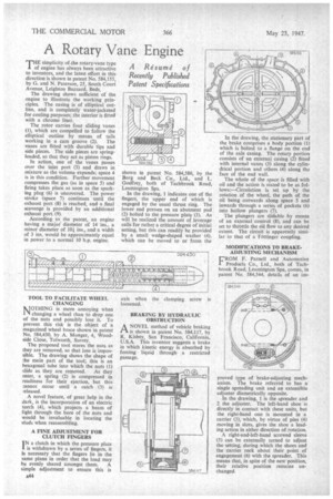
TI-OE simplicity of she rotary-vane type f engine has always been attractive to inventors, and the latest effort in this direction is shown in patent No. 584,155, by G. and N. Paterson, 25, South Court Avenue, Leighton Buzzard, Beds.
The drawing shows sufficient of the engine to illustrate the working principles. The casing is of elliptical outline, and is completely water-jacketed for cooling purposes; the interior is fitted with a chrome liner.
The rotor carries four sliding vanes (1), which are compelled to follow the elliptical outline by means of tails working in a cam groove (2). The vanes are fitted with durable tips and side pieces. The side pieces are springloaded, so that they act as piston rings.
In action, one of the vanes passes over the inlet port (3) and draws in mixture as the volume expands; space 4 is in this condition. Further movement compresses the gas (as in space 5) and firing takes place as soon as the sparking plug (6) is uncovered. The power stroke (space 7) continues until the exhaust port (8) is reached, and a final scavenge is provided by an additional exhaust port. (9).
According to the patent, an engine baying a major. diameter of 14 ins., a minor diameter of 10i ins., and a width of 3 ins, would be approximately equal in power to a normal 10 h.p. engine.
TOOL TO FACILITATE WHEEL CHANGING MOTHING is more annoying when 1' changing a wheel than to drop one of the nuts and possibly lose it. To prevent this risk is the object of a magazined wheel brace shown in patent No, 584,430, by A. Monger, 4, Woodside Close, Tolworth, Surrey.
The proposed tool stores the nuts as they are removed, so that loss is impossible. The drawing shows the shape of the main part of the tool; this is an hexagonal tube into which the nuts (1) slide as they are removed. As they enter, a spring (2) is compressed in readiness for their ejection, but this cannot occur until a catch (3) is released.
A novel feature, of great help in the dark, is the incorporation of an electric torch (4), which projects a beam of light through the bore of the nuts and would be invaluable in locating the studs when reassembling.
A FINE ADJUSTMENT FOR CLUTCH FINGERS I N a clutch in which the pressure plate is withdrawn by a series of fingers, it is necessary that the fingers lie in the same plane in order that the load may be evenly shared amongst them. A simple adjustment to ensure this is shown in patent No. 584,586, by the Borg and Beck Co., Ltd., and L. Godfrey, both of Tachbrook Road, Leamington Spa.
In the drawing, I indicates one of the fingers, the upper end of which is engaged by the usual thrust ring, The lower end presses on an abutment pad (2) bolted to the pressure plate (3). As will be realized the amount of leverage calls for rather a critical degree of initial setting, but this can readily be provided by a small wedge-shaped washer (4), which can be moved to or from the axis when the clamping screw is loosened.
BRAKING BY HYDRAULIC OBSTRUCTION
ANOVEL method of vehicle braking is shown in patent No. 584,117, by R. Kisbey, San Francisco, California, U.S.A. This inventor suggests a brake in which kinetic energy is absorbed by forcing liquid through a restricted passage.
In the drawing, the stationary part of the brake comprises a body portion (I) which is bolted to a flange on the end of the axle casing. The rotary portion consists of an external casing (2) fitted with internal vanes (3) along the cylindrical portion and others (4) along tha face of the end wall.
The whole of the space is filled with oil and the action is stated to be as follows:—Circulation is set up by the rotation of the wheel, the path of the oil being outwards along space 5 and inwards through a series of pockets (6) into hollow plungers (7).
The plungers are slidable by means of an external control (8), and can be set to throttle the oil flow to any desired extent. The circuit is apparently similar to that of a Fottinger coupling.
MODIFICATIONS TO BRAKEADJUSTING MECHANISM
CROM F. Parnell and Automotive Products Cp., Ltd., both of Tack' brook Road, Leamington Spa, comes, in patent No. 584,544, details of an im proved type of brake-adjusting mechanism. The brake referred to has a single spreading unit and an extensible adjuster diametrically opposite.
In the drawing, 1 is the spreader and 2 the adjuster. The left-hand shoe is directly in contact with these units, but the right-hand one is mounted in a carrier (3), which, by virtue of pins (4) moving in slots, gives the shoe a leading action in either direction of rotation.
A right-and-left-hand screwed sleeve (5) can be externally turned to adjust the setting, during which the shoes and the carrier rock about their point of engagement (6) with the spreader. This means that, in spite of the new position, their relative position remains unchanged.