


Patents Completed.
Page 30
If you've noticed an error in this article please click here to report it so we can fix it.
ANTI-SKID DEVICE-Prance—No. 23.715, dated 25th October, 1906.—Carried beside one of the tires (G), or between the same if two are employed, are a series of gripping bodies (A). Each gripping body is independent and, is connected by links (B) to a fixed part (H) secured to the felloe of the wheel. The links (B) are of such length that the outer face of each gripping body lies further from the centre of the wheel than the outer faces of the tires, but they lie in recesses which restrict their movement and thus prevent them from taking up a radial position. It follows, therefore, that, if skidding tends to take place in the direction of the arrow when the links are inclined in the position shown in the drawing, the weight of the vehicle will immediately be brought to bear upon the gripping body, and the latter, being in contact with the toad surface, it will prevent skidding. The links of alternate gripping bodies are oppositely inclined.
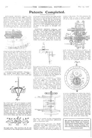
CONTROLLING LEVER.—Horsley.— No. 18,873, dated 23rd August, 1906— The lever (A) is carried at its lower end
by a ball joint (All arid engages a quadrant plate (131). In the quadrant plate, in. tersecting slots (C, C1) are provided, and, beneath the plate, are two members (11, respectively). The member iD) has in it an obliquely-disposed slot (DI) and in the member (E) is an oppositely disposed oblique slot (0). These two members are superimposed so that the slots (D1, Eli cross each other, and the rod (A) passes
through both. The members (D, E) are connected to the change-speed mechanism of tile, gear, and it will be seen that, as the lever (Ai is moved along the slots (C, the members (D, E) will be correspondingly moved. When the lever is in the central position both members are in their neutral positions, but when it is moved to either tetremity, of either of the slots, one or other of the gears is brought into actica.
IGNITION DEVICE.—Johnson and Another.—No. 27,27e, dated 90th December, 1905.—The object of this invention is to provide simple means whereby the moment of ignition may be delayed. The brake is effected by a lever (n) rocked by a rod if) which is pivoted to a camoperated rod (c). The lever (n) is normally maintained against the contact (p) by a spring (in) but is moved therefrom, to break contact, by the rod (f, r) as this rises. The portion (f) is pivoted to the rod (el, and can be moved towards the pivot (k) of the lever (n) so that it moves the lever at an earlier or later period according to its position, but the degree of displacement is always the same.
ELECTRICAL VEHICLE. — Greenwood and Another.—No. 9,103, dated 17th April, 1906.—Two independent elec., trical motors (h) are employed, each of which carries a pinion (g). The pinions (g) gear with toothed wheels (j) enclosed in a casing (c). The wheel-axle (di is divided, and one of the wheels (f) is mounted on one half of the axle, whilst
the other is carried on the corresponding half. By this construction differential gear is dispensed with.
SPEED GEAR.—Tourtel.—Nci. 13,257, dated 8th June, 1906.—According -to this invention, liquid is employed as the medium whereby any one of a series of wheels carried on the driving shaft-may be locked to the shaft. For this purpose, the driving shaft la) has a series of discs (/-2) on it, one of which is situated within each of the gear wheels (c, d and e). In these discs, spying-controlled plungers are mounted, and an eccentric chamber (m) is provided within the wheel. Passages (I) communicate between the periphery of the disc and the interior of the shaft (a). The shaft is hollow, and, sliding in it, is a plunger valve (f). The eccentric chambers (7n) within the wheels, and also the interior of the hollow shaft (a). are filled with oil, and the passages (1) are so arranged that, as the discs (e2i rotate, the plungers (j) circulate the liquid through the passages and through the shaft a). If, however, the plunger valve (f) be advanced so that it interrupts the communication between the passages (l) of any one disc and the interior-of the shaft, the liquid in the chamber (m) of the wheel belonging to that disc, cannot now be circulated, and thus it acts as a hydraulic lock between the wheel and shaft. Any one wheel may, thus, be brought into operation, whilst those whose passages are left in free communication with the interior of the shaft can rotate idly.