


Unit for Built-up Crankshafts
Page 58
If you've noticed an error in this article please click here to report it so we can fix it.
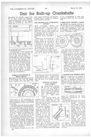
PATENT No. 649,383, comes from the Tatra concern of Czechoslovakia, and deals with a basic unit from which a crankshaft of any desired length may be built up. Cast iron is
the metal used; and bolting the method of uniting the parts. In the drawing, 1 is the crankpin and 2 the bosses for the main bearing. In view of the large diameter and narrow width of these bosses, it is presumed that they are intended for use with ball bearings. The casting is provided with bosses for the reception of machining centres (3) and is cored to form through ways for the lubrication system. Hole 4 is to receive the uniting bolts, three of which are used, spaced at 120 degrees. A claim made for this type of crankshaft is low cost of production.
TORQUE CONVERTERS IN SHEET METAL
PATENT No. 642,784, comes from the Ford Motor Co., Ltd., 88, Regent Street, London, W.1, and deals with
improvements in the construction of torque-converters, aimed at facilitating their manufacture in sheet metal instead of castings.
The patent shows the principle applied to the three units of a torque-converter, the pump, the turbine and the reaction member. The accompanying drawing shows how the pump member is built up from a number of individual pres sings (1). Each pressing forms not only a vane (2) but also part of the outer and inner peripheries (3 and 4).
The assemblage of units may be held together by spot-welding, although copper brazing is mentioned in connection with the other units. By forming the vanes in sheet metal, the frontal area presented to the fluid is reduced, with an increase in efficiency.
It is further claimed that the rela
lively simple fabrication and assembly involved make it possible to introduce mass-production methods.
THE DISTRIBUTION OF BRAKING EFFORT
AN arrangement whereby the driver's pedal-force can be apportioned between a hydraulic and a mechanical set of brakes is shown in patent No. 650,293, which comes from L. Chouings and the Automotive Products Co., Ltd., both of Tachbrook Road, Leamington Spa.
Referring to the drawing, the driver's pedal (1), when depressed, pushes on one end of a floating lever (2). The lever is pivoted on the end of the piston-rod of a master hydraulic cylinder (3) whilst the far end is pivoted to the rodwork (4) of a mechanical braking system.
The pedal can thus apply a force to both sets of brakes, the ratio between them being governed by the proportions of. the floating lever. A pair of flatmetal pieces (5) acts as a guide to maintain the lever in its proper working plane.
NOVELTY IN GEARPUMP DESIGN
AGEAR-PUMP intended for use in lubricating systems and similar fields is shown in patent No. 649,626, which comes from HobournEaton Manufacturing Co., Ltd., 9-11, High Street, Coventry.
The drawing shows the essential parts, comprising a driving rotor (1) and a driven one (2). The outer rotor has one more tooth than the inner one, and is eccen trically mounted, so that rotation produces a series of expanding spaces on one side and contracting ones on the other. Inlet and outlet ports (3 and 4) are provided in the end cover, and the pipework is attached to them. The pump can be made extremely thin so that it can be introduced
where space is particularly limited. The design of this pump is such that it can be adapted to be mounted as a part of an internal-combustionengine,
or of a transmission or other unit, receiving its drive from any convenient shaft.
LUBRICATING BOWDEN CABLES
AMEANS for applying lubricant to the inner wire of a Bowden cable is dealt with in patent No. 650,362, by Design and Development, Ltd., and R. Froggatt, both of Packington Hall Works, Whittington, Staffs.
The outer cable is assembled with an intermediate bush (1) placed at some convenient p oin t in its length. Surrounding the threaded diameter of the bush is a pair of screwed sleeves (2 and 3) which, when closed, form a dirt-proof seal. To lubricate the wire, the sleeves are screwed apart and lubricant applied via a cross-hole (4).
The patent also refers to a refinement to prevent the possibility of dirt entering via the filling aperture. The seal is in the form • of a spring strip depressed by the lubricant injector.
A CARBURETTER MODIFICATION hilANY carburetters are inclined to have a "flat spot" particularly at the point of changeover between the idling jet and the main jet, and many schemes have been propounded to overcome it. A simple solution is shown in patent No. 649,920, by the Carter Carburetter Corporation, St. Louis, Missouri, U.S.A.
The drawing shows the main nozzle projecting into the verituri of a down draught carburetter. The normal orifice is located on the underside at point 1, but the novelty consists of the addition of an extra hole (2) on the top side. According to the patentee, at low-suction low
engine speed conditions, air sweeps through both holes, carrying fuel with it
and enriching the mixture slightly. Under other conditions, the lower hole only is operative, the upper one being, it is stated, blocked by the fuel.