


An Extensible Trailer
Page 36
If you've noticed an error in this article please click here to report it so we can fix it.
A Resum of Patent Specifications That Have Recently Been Published
A N extensible trailer for carrying 1-1 loads 'of various lengths, such as timber, is shown in patent No. 667,018, by J. Drewry, and Hands (Letchworth),, Ltd.,' both of New Icknield Way, Letchworth, Herts. The trailer, in its shortest position, forms a flat platform suitable for carrying normal loads. Shown in the drawing as a semitrailer, the vehicle is made in two parts united by sliding frame-members. The length is adjusefinite steps, locking being performed by a dual bolting mechanism operated by a lever (1); bosses (2) indicate the available positions. The rear brake is operated via an ingenious cable mechanism, which is unaffected by change of length. The u cable (3) is led around pulleys on a pivoted arm (4) and is secured at the rear end of the frame. The brake gear is attached to the pivot of the innermost pulley. In operation, the pulley rocks the arm which transmits the motion to the brake, the cable length remaining constant, irrespective of the position along the frame. If air brakes be used, the supply pipe would be arranged lathe same manner.
PROGRESS IN DISC-TYPE BRAKE DESIGN
TO give a sell-adjusting action to a disc brake is the object of a design shown in patent No. 566,744, by Bendix Aviation Corporation, South Bend, Indiana, U.S.A. Referring to the drawing, 1 is the rotary disc, which is composed entirely of friction fabric, located by being a splined fit in the drum. The disc runs between a pair 'of stationary plates (2 and 3) The latter is axially sliclable, and may be pressed into contact by the admission of pressure fluid to an extensible rubber tube (4). , The automatic take-up consists of special spring-steel washers (5), riveted to the ,slicing and emaracing spacers consisting of plungers. (6). These washers, by means of internal tongues, readily. permit " on " movement, but exert opposition to the "off' stroke, so that the movable plate is always left close to its active position. The necessary working clearance is provided by leaving the plungers with a little end-play.
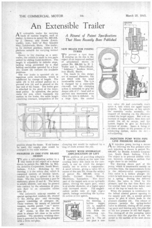
NEW MEANS FOR FIXING TYRES
To prevent a tyre from creeping on its rim is the object of an improved method of attachment shown in patent No. 566,501 by H. J. Waller and L. Ffitch-Hayes, Solsbury," Swallow Street,. Iver Heath, 13ucks. The beads in -this design are of unequal diameter, but are fitted with the usual inextensible wires. The tyre . is clamped laY a removable rim-wall, but the clamping action is extended to grip the deeper side of head and so prevent any movement even when the tyre is deflated. In a large tyre, the central clamping nut would be replaced by a ring of studs around the rim.
TAPPET WITH HYDRAULIC . AMPLIFICATION OF LIFT
TEE problem of providing adequate • 1 cam lift, without at. the same time creating heavy side loads on the camshaft, is One on which the designer usually has to strike a coniprornise. A novel scheme, giving a valve lift in excess of the cam lift, forms the subject of patent No. 566,959, from T. Hindle, Cartmel Street, • • Witton, Blackburn, Lancashire. T be lower part of the tappet acts as an hydraulic piston, driving the upper part, which is of smaller diameter, at a higher speed with increased stroke The magnification occars only at high engine speeds, leakage overriding the hydraulic action at low speeds. way valve (3) and eventually .reach space 4, into which the upper' tappet projects. In operation, at low speeds the assembly works normally, the trapped oil escaping via the clearance around the larger tappet. But with an increase of engine speed, time does not permit the oil. to escape, and the System begins to give an hydraulic increase of stroke. Space 4, being at .all times subject to the pressure of the lubricating system, makes the devi self-adjusting.
INJECTION PUMP WITH PIPE LINE PRESSURE RELEASE AN injection pump having a means for relieving the line pressure after each injection is shown in patent No. 566,957, by tendix Aviation Corporation, South Bend, Indiana, U.S.A. The object is to prevent dribble without, however, creating a suction that might draw in air bubbles. The drawing shows part of the pump, which is constructed mainly on orthodox lines, the improvements lying in the delivery-valve arrangements. This valve is a hollow plunger (1) which is held down on a conical seatingby a spring. During the delivery stroke, the, valve is lifted by the pressure, and the fuel then flows into the central bore (via cross holes) and out of the top to reach the exit. When the pressure is terminated by the helical control groove opening to the supply port (2), a second groove opens to port '3 which leads to th(1 pressure chamber (4). The release of pressure permits the spring-loaded valve to descend, closing oil the pumping space and leaving, only. the pipe-line at the low pressure of the fuel supply. The closing-off Of the pumping space ensures that the pipe-line is not ubjected to the suction of the next downstroke.