


Patents Completed.
Page 22
If you've noticed an error in this article please click here to report it so we can fix it.
SPRING WHEEL. — Rhone. — No. 25,317, dated 31st October, 1910.—This invention is in connection with that type of spring wheel in which the tires consist of a series of blocks of rubber or similar flexible material arranged circumferentially on the wheel and controlled in dependently by springs. The essential feature of the invention consiets in the arrangement, whereby each of the resilient blocks of the wheel is connected to its spring by means of a ball-andsocket joint which enables the bearing surface of the spring in question always to be maintained at right angles to the axis of the spring whatever obliquity may be imposed upon it by the inclination of the block as the wheel rolls along. The spring is thus submitted only to normal strains and any torsion and consequent breaking is avoided. The blocks forming the tire are fixed in shoes, the inner side of which have spherical recesses in which rest and are free to rotate balls formed on the centres of discs, One end of the spring bears against a disc, and the other end rests either on the metal rim of the wheel or against a similar disc attached to the rim. A small flange is provided on the two discs to ensure the central location of the spring. An outward movement of the shoes under the action ci the spring is limited by means of crossbars or rods engaging a flange on the inner edge of the shoes.
T A XIMETE R. —Appl eten.—No. 4,808, dated 25th February, 1910.—This inven.tion has for its principal object the provision of a taximeter or an attachment for a taximeter whereby the registering of " extras " will be eflected automatically. The invention consists broadly it providing electrical or mechanical apparatus which must be operated by the driver to release the extra seats in the
seat has been released it remains released until the flag is raised again at the end of the hire. This movement of the flag telt:Ides the seat so that it cannot be released again without registering on the taximeter. In the drawings, this arrangement is shown for use with two extra seats; two separate handles are provided, one centrolling each seat, and they are interlocked so that either one can be operated independently.
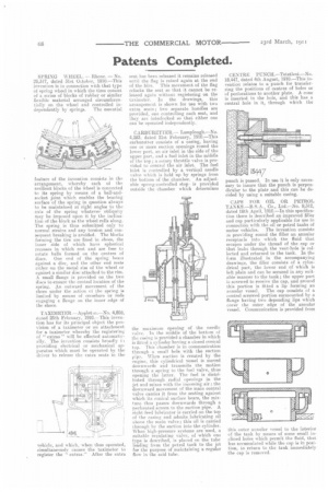
CARBURETTER.— Lamplough.—No. 4,283, dated 21st February, 1910.—This carburetter consists of a casing, having one or more suction openings round the lower part, an air inlet in the side of the tipper part, and a fuel inlet in the middle of the top; a rotary throttle valve is provided to control the air inlet. The fuel inlet is controlled by a vertical needle valve which is held up by springs from the bottom of the chamber. An adjustable spring-controlled stop is provided outside the chamber which determines
the maximum opening of the needle valve. In the middle of the bottom of the cueing is provided a chamber in which is fitted a cylinder having a closed conical top. This chamber is in communication through a small hole with the suction pips. When suction is created by the engine, this cylindrical vessel is moved downwards and transmits the motion through a spring to the fuel valve, thus opening the latter. The fuel is distributed through radial openings in the jet and mixes with the incoming air ; the downward movement of the main central valve carries it from the seating against which its conical surface bears, the mixture tints passes downwards through a perforated screen to the suction pipe. A sight-feed lubricator is carried on the top of the casing and admits lubricating oil above the main valve; this oil is carried through by the suction into the cylinder. When high-pressure systems are used, a suitable regulating valve, of which one type is described, is placed on the tube leading from the petrol tank to the jet for the purpose of maintaining a regular flow in the said tube,
CENTRE PUNCH.—Tetetleni.—No. 18,447, dated 4th August, 1910.—This relates to a punch for transferring the positions of centres of holes or of perforations to another plate. A cone is inserted in the hole, and this has a central hole in it, through which the punch is passed. In use it is only necessary to insure that, the punch is perpendicular to the plate and this can be decided by using a suitable easing.
CAPS FOR OIL OR PETROL TANKS.—B.S. A., Co., Ltd.—No. 9,312, dated 18th April, 1910.—In this specification there is described an improved filler and cap particularly applicable for use in connection with the nil or petrol tanks of motor vehicles. The invention consists In providing round the filler an annular receptacle into which the fluid that etecapes under the thread of the cap or that leaks through the vent-hole is collected and returned to the tank. In the form illustrated in the accompanying drawings, the filler consists of a cylindrical part, the lower end of which is left plain and can be secured in any suitable manner to the tank; the upper part is screwed to receive the cap, and around this portion is fitted a lip forming an annular vessel. The cap consists of a central screwed portion surmounted by a flange having two depending lips which cover the outer edge of the annular vessel. Communication is provided from