


Resilient Engine Mountings
Page 62
If you've noticed an error in this article please click here to report it so we can fix it.
A Resume of Recently Published Patent Specifications THE names of Humber, Ltd., and Ti. C. Ord appear in patent No. 392,256, in which means for resiliently mounting engines to prevent periodic vibrations from being transmitted to the frame are described. At the front end of the engine two bosses are formed, which are situated close together, and one boss surrounding the driven shaft of the gearbox is provided at the rear.
The front end supports consist of two brackets, which are bolted to a crossmember. Rubber discs (8) are placed on each side of the central partition, and bolts (9) can be used to give them any desired degree of compression, which causes them to expand in the bosses of the engine.
The rear mounting is by means of a ring of soft rubber.
Welded-wire Spokes.
PATENT No. 392,049, by the Kelsey Hayes Wheel Corporation, Military Avenue, Detroit, relates to a method of making wheels in which the spokes are welded to the hub and to the rim. The object of the invention is stated to be to provide a more efficient weld, to reduce the flash, and so almost to abolish hand labour in cleaning the parts.
The spokes are butted at both ends by an upsetting process, and are so formed that they locate themselves on a raised portion on the hub or rim, at the same time providing a smaller initial area of contact which is less than that of the completed weld. The enlarged ends provide a means for pressing the ends in contact without gripping them with a jaw, which in some cases will bite into the spoke. The illustrations show a spoke before and after welding.
Securing Valve Seatings.
IN patent No. 392432, W. A. Oubridge, Parklands, Park Road, Coventry, several examples are shown of means for holding rings in place for valve seatings, by means of a ring of ductile metal, such as mild steel, aluminium or alloys of metals.
Bib
In each case the boring in the cylinder has an undercut, and the valve seating has a groove cut in it to receive the ductile ring, which is split to enable it to be introduced into the undercut. Its section is then altered by pressure so that it engages with the groove in the seating ring.
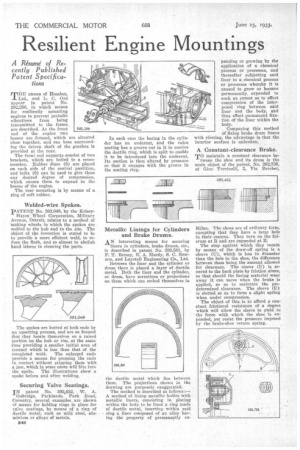
Metallic Linings for Cylinders and Brake Drums.
AN interesting means for securing liners in cylinders, brake drums, etc., is described in patent No. 392,581, by F. T. Bersey, E. A. Hardy, S. C. Newson, and Laystall Engineering Co., Ltd. Between the liner and the cylinder or drum there is placed a layer of ductile metal. Both the liner and the cylinder, or drum, have serrations or projections on them which can embed themselves in the ductile metal which lies between them. The projections shown in the drawing are purposely exaggerated.
The method is described as follows :A method of lining metallic bodies with metallic liners, consisting in placing within the body to be lined a ring made of ductile metal, inserting within said ring a liner composed of an alloy having the property of permanently ex panding or growing by the application of a chemical process or processes, and thereafter subjecting said liner to a. chemical process or processes whereby it is caused to grow or become permanently_ expanded to such an extent as to effect compression of the interposed ring between said liner and the body, and thus effect .permanent fixation of the liner within the body.
Comparing this method of fixing brake drum liners with riveting, the advantage is that the interior surface is unbroken.
A Constant-clearance Brake.
To maintain a constant clearance between the shoe and its drum is the main object of the patent, No. 392,738, of Gino Tnrrinelli, 2, Via Berchet,
Milan. The shoes are of ordinary form, excepting that they have a large hole in their centres. They turn on the fulcrum at R and are expanded at B. The stop against which they recede by means of the draw-off spring is a sleeve (U), which is less in diameter than the hole in the shoe, the difference between them being the amount allowed for clearance. The sleeve (U) is secured to the back plate by friction alone, so that should the facing material wear away it can move when the brake is applied, so as to maintain the predetermined clearance. The sleeve (U) is slotted so as to form a slight spring when under compression.
The object of this is to afford a constant frictional resistance of a degree which will allow the sleeve to yield to the force with which the shoe is expanded, yet resist the pressure imposed by the brake-shoe ieturn spring.